Universal tensegrity joints for human exoskeleton

Active Publication Date: 2017-07-27
EKSO BIONICS
View PDF3 Cites 11 Cited by
  • Summary
  • Abstract
  • Description
  • Claims
  • Application Information

AI Technical Summary

Benefits of technology

The patent text describes devices and methods that make exoskeleton joints much more flexible. This improves the performance of the exoskeleton and allows it to move more easily in different terrains and movements. The devices also make the exoskeleton lighter and fit better to the user.

Problems solved by technology

This requires a degree of rigidity, seen in the joints of current exoskeletons, that can limit the range of motion of some exoskeleton joints.
By limiting the flexibility at these joints, the mobility and maneuverability of the exoskeleton is reduced, thereby limiting the usefulness of the exoskeleton in certain applications.
This is an issue in both passive weight-bearing exoskeletons and powered exoskeletons.
This greatly limits the degrees of freedom of one rigid exoskeleton member relative to the adjoining exoskeleton member.
As a result, the bottom of an exoskeleton foot cannot compensate for a slope in the coronal plane, making current exoskeletons incapable of walking on many types of terrain.
As another example, the inability (or reduced ability) of exoskeleton ankle and hip joints to rotate in the transverse plane makes turning a walking or standing exoskeleton difficult.

Method used


Image

  • Universal tensegrity joints for human exoskeleton
  • Universal tensegrity joints for human exoskeleton
  • Universal tensegrity joints for human exoskeleton

Examples


first embodiment

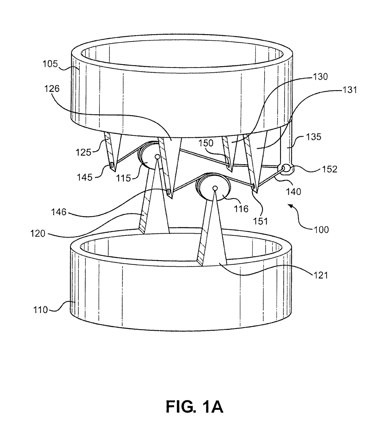
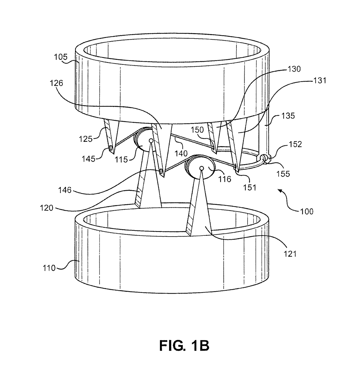
[0036]With reference now to FIG. 1A, the present invention is shown. In particular, a simplified exoskeleton joint is labeled 100. Joint 100 connects an upper compression member 105 to a lower compression member 110, with upper compression member 105 being supported over lower compression member 110. Joint 100 includes a right pulley 115 connected to lower compression member 110 by a right support 120 and a left pulley 116 connected to lower compression member 110 by a left support 121. Right support 120 and left support 121 are directly coupled to lower compression member 110. Similarly, a right front support 125, a left front support 126, a right rear support 130, a left rear support 131 and rear guide 135 are directly coupled to upper compression member 105. Joint 100 also includes a tensile member 140 that is directly coupled to right front support 125 and left front support 125 at a right attachment 145 and a left attachment 146, respectively. Tensile member 140 is wrapped arou...

second embodiment

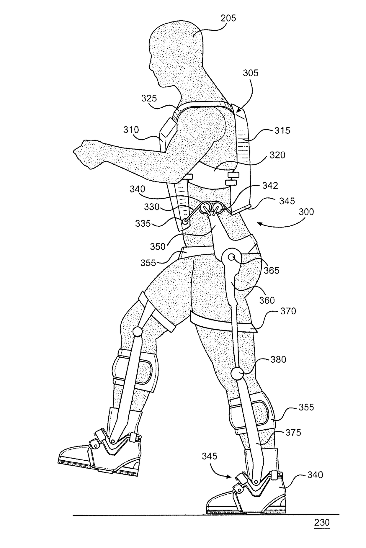
[0043]FIGS. 2A-H show an exoskeleton ankle joint 200 constructed in accordance with the present invention. With initial reference to FIGS. 2A and 2B, joint 200 is shown in connection with a right foot of an exoskeleton wearer (or user) 205. Specifically, a rigid boot support 210 is directly coupled to a boot 215 worn by wearer 205. A strap 220 selectively couples boot support 210 to boot 215 while also limiting ankle roll for the wearer's right foot. Both boot 215 and a ground interaction structure 225 directly coupled to boot support 210 are in contact with a support surface 230 on which wearer 205 is standing. A tensile member 235 is directly coupled to a left front support 240 at a left attachment point 245. Tensile member 235 is wrapped around a left pulley 250 and passes through a left rear support 255 into a tensile member guide 260. Left pulley 250 rotates about a bearing 265, which connects left pulley 250 to a left lower leg support 270. In FIG. 2B, a portion of left lower ...


PUM


Abstract

An exoskeleton includes first and second compression members configured to be coupled to a wearer of the exoskeleton. A tensegrity joint connects the first compression member to the second compression member, the joint including a tensile member having a first end and a second end. The first end is coupled to the first compression member on a first side of the joint, and the second end is coupled to the first compression member on a second side of the joint opposite the first side.

Description

CROSS REFERENCE TO RELATED APPLICATIONS[0001]This application claims the benefit of U.S. Provisional Application No. 62 / 193,919, which was filed on Jul. 17, 2015 and titled “Universal Tensile Joints for Human Exoskeleton”. The entire content of this application is incorporated herein by reference.GOVERNMENT LICENSE RIGHTS[0002]This invention was made with government support under Contract H92222-15-C-0025 awarded by the United States Special Operations Command. The government has certain rights in the invention.FIELD OF THE OF THE INVENTION[0003]The present invention relates to a device and method that augments a user's carrying capacity and strength, increasing performance and aiding in the prevention of injury during the execution of certain load-bearing or strength-requiring tasks. More particularly, the present invention relates to a device suitable for use by a person engaging in heavy tool use or weight-bearing tasks, the device comprising a set of artificial limbs and related...

Claims


Application Information

Patent Timeline
IPC IPC(8): A61H3/00A61F2/66A61F2/60
CPCA61H3/00A61F2/604A61F2/605A61F2/66A61F2002/5038A61H2205/12A61H2201/1642A61H2201/165A61H2205/08A61H2205/10A61H2201/1621A61H1/0255A61H1/0266A61H2201/0165A61H2201/0192A61H2201/169B25J9/0006B25J17/00
Inventor HUGHES, MIKEANGOLD, RUSSDONVICKERS, JEFFROAN, BRADLEYAMUNDSON, KURTFLEMING, NICHOLAS
Owner EKSO BIONICS
Why Eureka
Try Eureka