State detection sensor

Active Publication Date: 2017-07-27
DENSO CORP
View PDF5 Cites 11 Cited by
  • Summary
  • Abstract
  • Description
  • Claims
  • Application Information

AI Technical Summary

Benefits of technology

[0008]With the above construction, the first heat flux sensor, the thermal buffer body having the predetermined heat capacity, the second heat flux sensor and the heat releasing body having the predetermined heat capacity are arranged in this order from the sensing subject side. Therefore, it is possible to limit an influence of a change in the atmosphere, which is caused by the release or accumulation of the heat at the heat releasing body exposed to the atmosphere, to the first and second heat flux sensors. Furthermore, the thermal buffer body having the predetermined heat capacity is placed between the first heat flux sensor and the second heat flux sensor. Therefore, in the case where the abnormal heating of t

Problems solved by technology

However, in this type of state detection sensor, the temperature sensors are exposed to the surrounding atmosphere, so that this type of state detection sensor is susceptible to the influence of the temperature change caused by the surrounding atmosphere.
Therefore, in the above-described state detection sensor, there is a disadvantage of that the temperature (state) of the sensing su

Method used


Image

  • State detection sensor
  • State detection sensor
  • State detection sensor

Examples


first embodiment

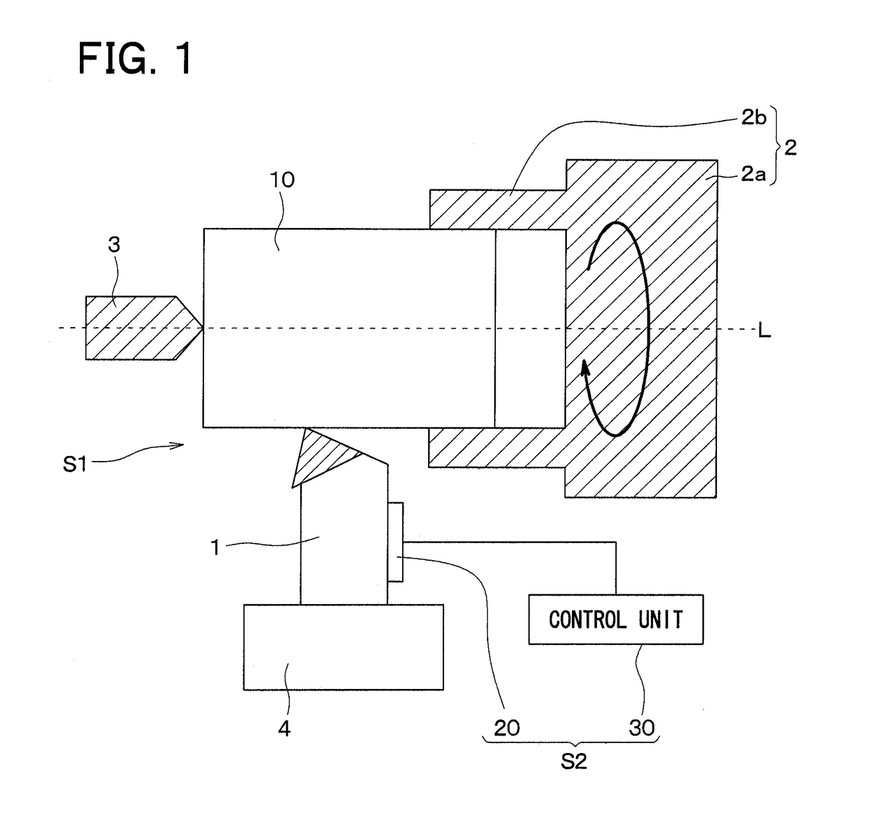
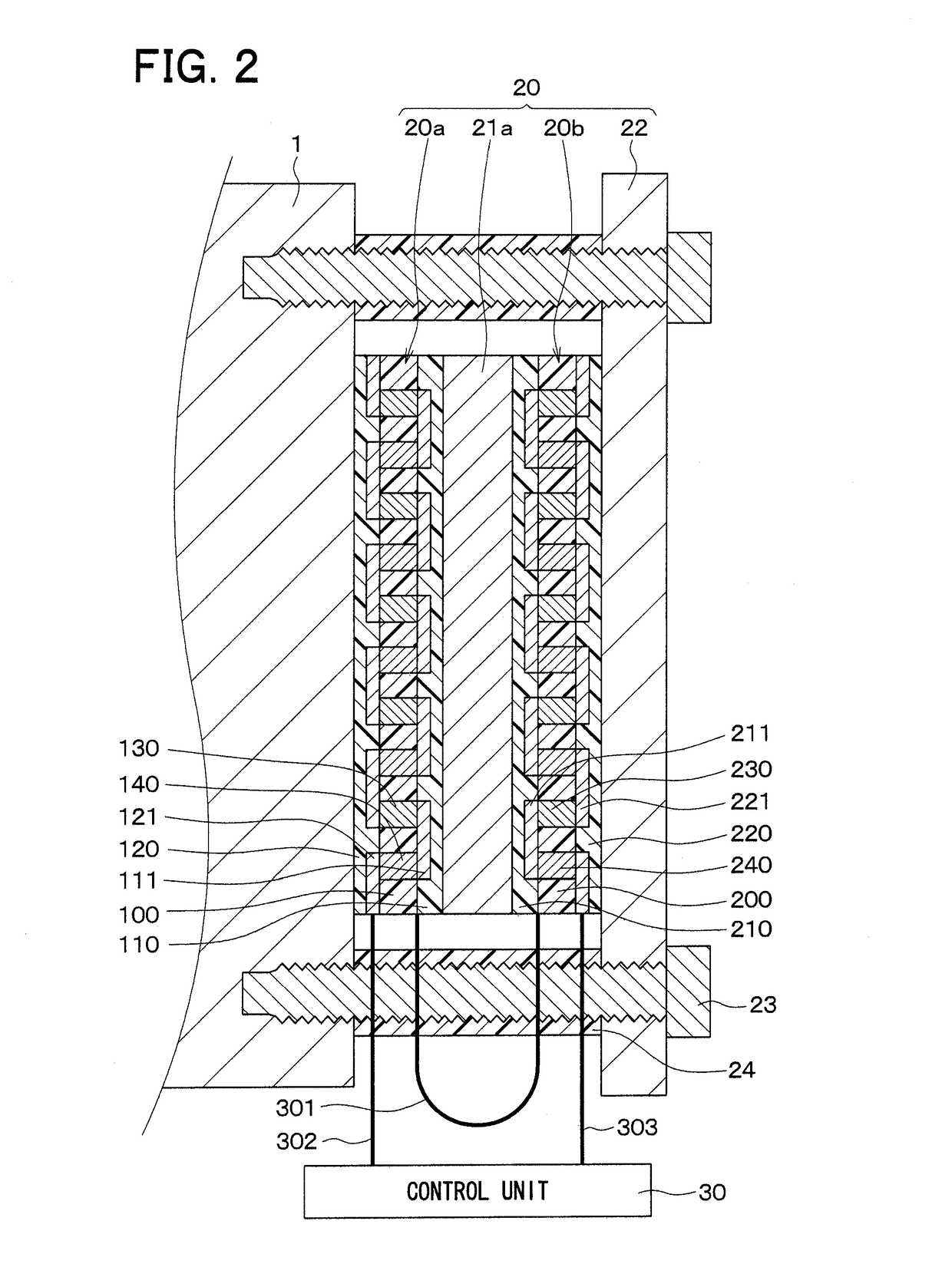
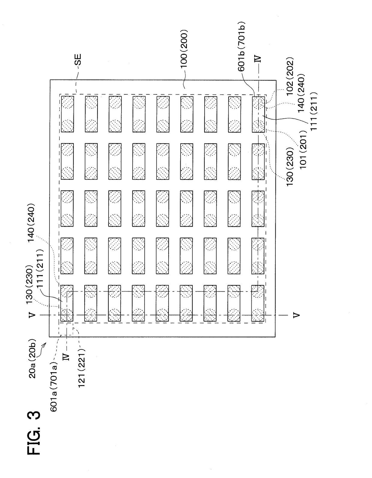
[0029]A first embodiment of the present disclosure will be described with reference to the drawings. In the present embodiment, there will be described an example of an abnormality determining device, which determines an abnormal heat generation (state) of a cutting device through use of a state detection sensor of the present disclosure. As shown in FIG. 1, the cutting device S1 includes a blade 1 and a pair of first and second jigs 2, 3. In the present embodiment, the blade 1 is fixed to a support member 4. The first jig 2 includes a main body 2a and three holding portions 2b (only two of the holding portions 2b are shown in FIG. 1), which project from the main body 2a in a common direction. A processing subject member 10 is clamped with the three holding portions 2b. The second jig 3 is placed on an opposite side of the processing subject member 10, which is opposite from the side where the processing subject member 10 is clamped by the first jig 2, such that the second jig 3 coo...

second embodiment

[0085]A second embodiment of the present disclosure will be described. In the present embodiment, a heat receiving body is placed on an opposite side of the first heat flux sensor 20a, which is opposite from the thermal buffer body 21a. The rest of the present embodiment is the same as that of the first embodiment and thereby will not be described for the sake of simplicity.

[0086]In the present embodiment, as shown in FIG. 9, the state detection sensor 20 includes the heat receiving body 25, which is placed on the opposite side of the first heat flux sensor 20a, which is opposite from the thermal buffer body 21a. That is, the state detection sensor 20 includes the heat receiving body 25, which is placed between the blade 1 and the first heat flux sensor 20a. Similar to the thermal buffer body 21a and the heat releasing body 22, the heat receiving body 25 is in a form of a planar plate that has a predetermined heat capacity (thermal resistance) and is made of, for example, metal (e.g...

third embodiment

[0089]A third embodiment of the present disclosure will be described. In the present embodiment, additional heat flux sensors and additional thermal buffer bodies are provided to the structure of the first embodiment. The rest of the present embodiment is the same as that of the first embodiment and thereby will not be described for the sake of simplicity.

[0090]In the present embodiment, as shown in FIG. 10, the state detection sensor 20 includes third and fourth heat flux sensors 20c, 20d and thermal buffer bodies 21b, 21c in addition to the first and second heat flux sensors 20a, 20b and the thermal buffer body 21a. In the state detection sensor 20, the first heat flux sensor 20a, the thermal buffer body 21a, the second heat flux sensor 20b, the thermal buffer body 21b, the third heat flux sensor 20c, the thermal buffer body 21c, the fourth heat flux sensor 20d and the heat releasing body 22 are arranged one after another in this order from the blade 1 side.

[0091]The constructions...


PUM


Abstract

A first heat flux sensor, which outputs a first sensor signal according to a heat flux passing therethrough, a second heat flux sensor, which outputs a second sensor signal according to a heat flux passing therethrough, a thermal buffer body, which has a predetermined heat capacity, and a heat releasing body, which has a predetermined heat capacity, are provided, and the first heat flux sensor, the thermal buffer body, the second heat flux sensor and the heat releasing body are arranged in this order from a sensing subject side. The first sensor signal, which corresponds to the heat flux between the sensing subject and the thermal buffer body, is outputted from the first heat flux sensor, and the second sensor signal, which corresponds to the heat flux between the thermal buffer body and the heat releasing body, is outputted from the second heat flux sensor.

Description

CROSS REFERENCE TO RELATED APPLICATION[0001]The present disclosure is based on and incorporates herein by reference Japanese Patent Application No. 2014-213680 filed on Oct. 20, 2014.TECHNICAL FIELD[0002]The present disclosure relates to a state detection sensor that senses a state of a sensing subject.BACKGROUND ART[0003]There has been proposed an abnormality determining device that determines abnormal heating of a sensing subject based on a sensor signal outputted from a state detection sensor, which detects a state of the sensing subject (see, for example, the patent literature 1). That is, the abnormality determining device includes the state detection sensor that has a temperature sensor, which senses a temperature of a surface of an upper portion of the sensing subject, and a temperature sensor, which senses a temperature of a surface of a lower portion of the sensing subject. The sensing subject is a subject that generates convection through the heat generation. The abnormali...

Claims


Application Information

Patent Timeline
IPC IPC(8): G01K3/14G01K17/00
CPCG01K17/00G01K3/14G01K3/08G01K17/20G01K7/02
Inventor GOUKO, NORIOSAKAIDA, ATUSITANIGUCHI, TOSHIHISAOKAMOTO, KEIJISHIRAISHI, YOSHIHIKO
Owner DENSO CORP
Why Eureka
Try Eureka