Optical scanning type object detection device

a detection device and optical scanning technology, applied in the direction of distance measurement, instruments, surveying and navigation, etc., can solve the problems of difficult to accurately identify the position of a distant object from the viewpoint of resolution, the detection range around the rotation axis of the mirror unit is limited, and the cost becomes very large, so as to achieve the effect of effectively detecting an object invading the detection area, simple configuration and low cos

Active Publication Date: 2017-08-03
KONICA MINOLTA INC
View PDF3 Cites 22 Cited by
  • Summary
  • Abstract
  • Description
  • Claims
  • Application Information

AI Technical Summary

Benefits of technology

[0011]One or more embodiments of the invention provide an optical scanning type object detection device having a wide detection area exceeding, for example, 180° and being capable of effectively detecting an object invading the detection area with a relatively simple configuration and low cost.

Problems solved by technology

However, it is difficult to accurately identify a position of a distant object from the viewpoint of resolution.
However, with a configuration disclosed in JP 2015-180956 A, detection range around the rotation axis of the mirror unit is limited.
However, in the optical measurement device in the specification of U.S. Pat. No. 7,969,558, due to providing a plurality of light sources and light receiving elements, cost becomes very large, and how the light sources and light receiving elements can be power-supplied and controlled from the outside.
For example, if a plurality of the light sources and the light receiving elements are attempted to be power-supplied or communication-controlled from the outside by using a contact type rotary connector or the like, the configuration becomes large, and also noise generation or treatment difficulty occurs.
Although it may be considered that these connectors are applied to the technique disclosed in the specification of U.S. Pat. No. 7,969,558, cost may increase, or the configuration may be complicated.

Method used


Image

  • Optical scanning type object detection device
  • Optical scanning type object detection device
  • Optical scanning type object detection device

Examples


first example

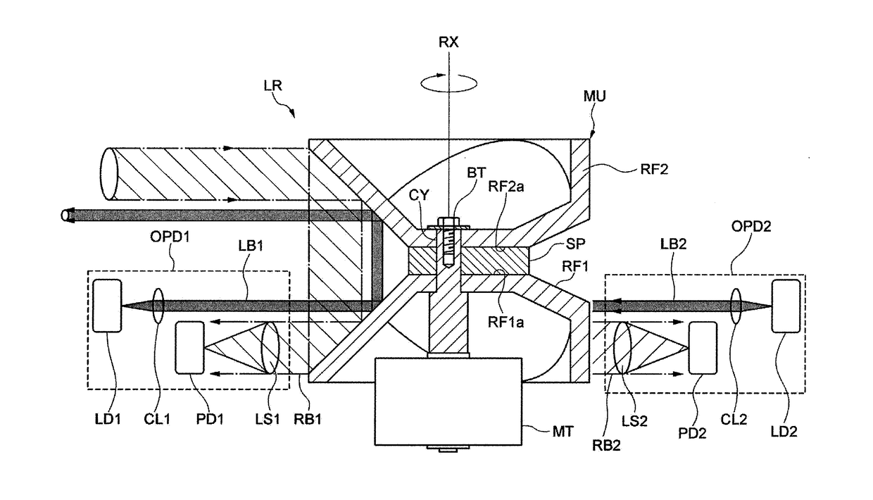
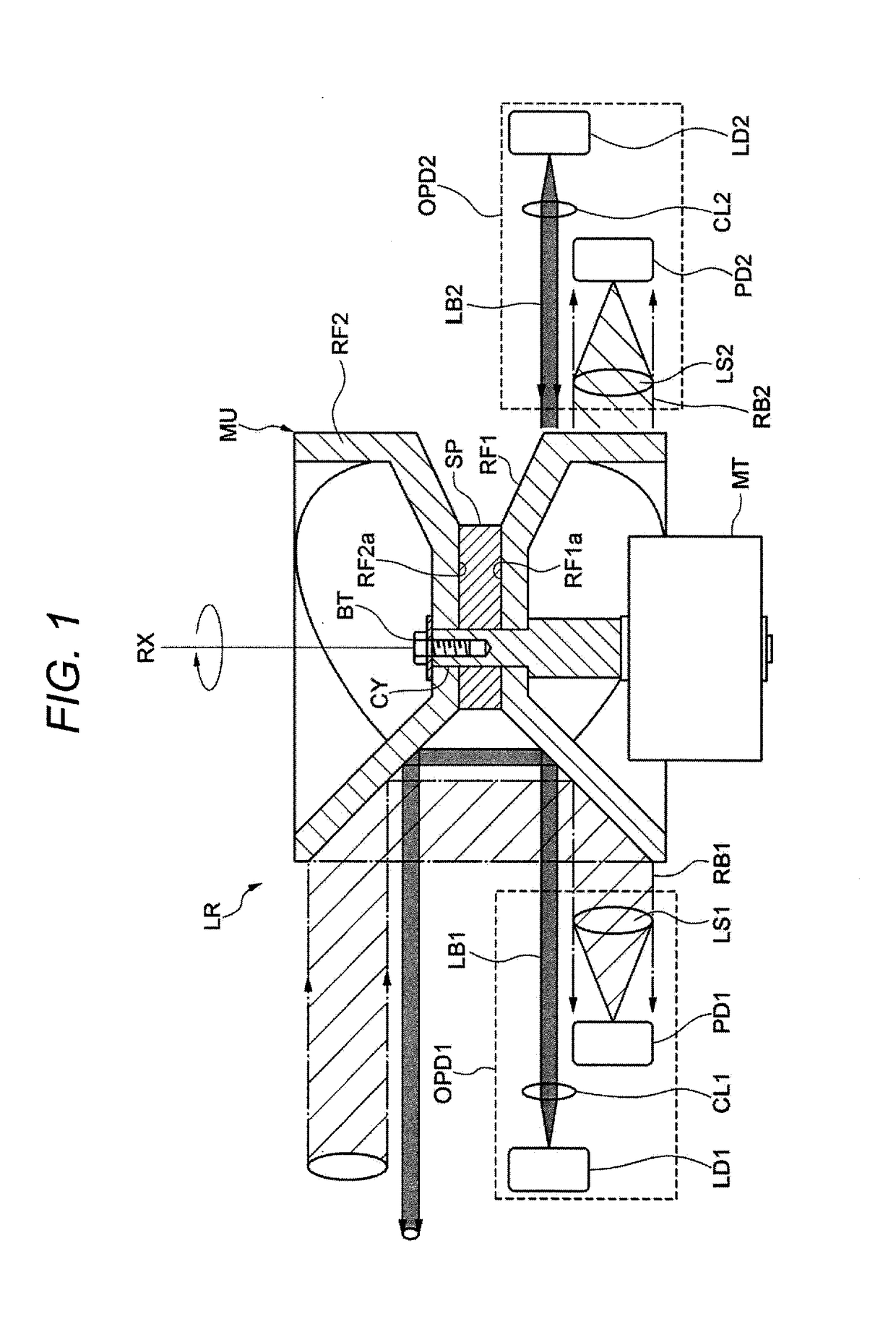
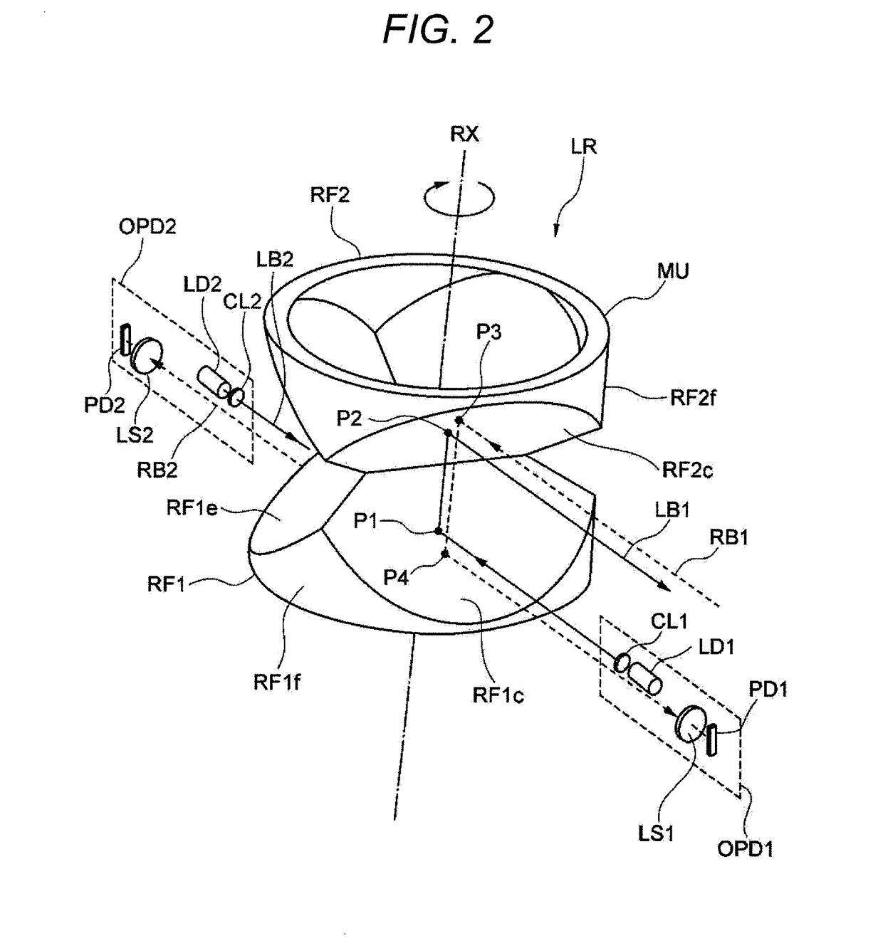
[0046]FIG. 1 is a cross-sectional diagram illustrating a laser radar LR as an optical scanning type object detection device in accordance with one or more embodiments. FIG. 2 is a perspective diagram illustrating main components of the laser radar LR in accordance with one or more embodiments. Herein, laser beams (solid lines) being directed to an object and reflected beams (one-dot dashed lines) from the object are illustrated by only respective optical axes. FIG. 3A is a schematic diagram illustrating a second reflecting member constituting a mirror unit as viewed in a direction along a rotation axis, and FIG. 3B is a diagram illustrating a first reflecting member constituting the mirror unit as viewed in the direction along the rotation axis. Slant angles of the reflection plane with respect to the rotation axis are attached to the respective reflection planes.

[0047]In FIG. 1, the laser radar LR is configured to include a first light emitting / receiving unit OPD1, also referred to...

example 1

[0072]FIG. 9 is a side view of Example 1 illustrating only a mirror unit MU, a semiconductor laser LD1, and a collimation lens CL1 corresponding to the embodiments of FIGS. 1 to 6, and FIG. 10 is a diagram of a configuration of FIG. 9 cut along line X-X as viewed in the arrow direction. In the mirror unit MU, portions other than the reflection planes are mainly omitted.

[0073]In Example 1, the beam spread angle of the laser beam flux LB1 emitted from the semiconductor laser LD1 is 28° (full width at half maximum), and the laser beam flux is allowed to pass through the collimation lens CL1 with a focal length of f=6 mm to be converted into a substantially parallel beam with a beam diameter of φ=5.5 mm (when the intensity at the center is 100%, a diameter at a position where the intensity is 95%). The parallel beam is incident on the reflection plane RF1c of the mirror unit MU along the direction perpendicular to the rotation axis RX. At this time, the incident position is set to the p...

example 2

[0075]FIG. 11 is a side view of Example 2 illustrating only a mirror unit MU, a semiconductor laser LD1, and a collimation lens CL1 corresponding to the embodiments of FIGS. 7A, 7B, and 8, and FIG. 12 is a diagram illustrating a configuration of FIG. 11 cut along line XII-XII as viewed in an arrow direction. In the mirror unit MU, mainly reflection planes are illustrated, and other components are omitted.

[0076]In Example 2, the beam spread angle of the laser beam flux LB1 emitted from the semiconductor laser LD1 is 28° (full width at half maximum), and the laser beam flux is allowed to pass through the collimation lens CL1 with a focal length of f=6 mm to be converted into a substantially parallel beam with a beam diameter of φ=5.5 mm (when the intensity at the center is 100%, a diameter at a position where the intensity is 95%). The parallel beam is incident on the reflection plane RF1c of the mirror unit MU along the direction perpendicular to the rotation axis RX. At this time, t...


PUM


Abstract

An object detection device includes a first optical transceiver that generates a first beam flux and receives a scattered portion of the first beam flux, a second optical transceiver that generates a second beam flux and receives a scattered portion of the second beam flux, and a mirror unit that rotates around a rotation axis. The first beam flux is reflected by the mirror unit and is scanned based on the rotation of the mirror unit, and the scattered portion of the first beam flux is generated by scattering of the first beam flux by an object. The scattered portion of the first beam flux is reflected by the mirror unit before being received by a light receiving portion of the first optical transceiver, and the second beam flux is reflected by the mirror unit and is scanned based on the rotation of the mirror unit.

Description

[0001]The entire disclosures of Japanese Patent Application No. 2016-018723 filed on Feb. 3, 2016 and No. 2016-178440 filed on Sep. 13, 2016 including description, claims, drawings, and abstract are incorporated herein by reference in its entirety.BACKGROUND OF THE INVENTION[0002]Field of the Invention[0003]The present invention relates to an optical scanning type object detection device capable of detecting an object or the like which invades a detection area.[0004]Description of the Related Art[0005]In recent years, as crime prevention awareness rises, there is an increasing demand for a monitoring system capable of accurately detecting an object that has entered the detection area. As a method of detecting such an object, a radio wave radar which transmits radio waves to detect reflected waves has been proposed. However, it is difficult to accurately identify a position of a distant object from the viewpoint of resolution.[0006]In contrast, WO 2011 / 021103 A discloses a TOF (time ...

Claims


Application Information

Patent Timeline
Patent Type & Authority Applications(United States)
IPC IPC(8): G01S7/481G01S17/87
CPCG01S7/4815G01S7/4817G01S17/42G01S17/87G01S7/003G01S7/4818G01S2007/4977
Inventor HAYAKAWA, SHUHEINAGASAWA, HIKARUKAGEYAMA, MASASHIISHIKAWA, RYOUTA
Owner KONICA MINOLTA INC
Why Eureka
Try Eureka