Power factor improving converter, and power supply device including power factor improving converter

a converter and power factor technology, applied in the direction of electric variable regulation, process and machine control, instruments, etc., can solve the problems of increasing switching loss, increasing choke iron loss, increasing choke copper loss, etc., to reduce voltage applied, reduce choke, and reduce the effect of chok

Active Publication Date: 2017-08-03
SHINDENGEN ELECTRIC MFG CO LTD
View PDF6 Cites 9 Cited by
  • Summary
  • Abstract
  • Description
  • Claims
  • Application Information

AI Technical Summary

Benefits of technology

[0022]The power factor improving converter and the power supply device including the power factor improving converter of the present invention have the following effects.
[0023]First, the voltage applied to the choke decreases, and the apparent frequency increases, thereby enabling the miniaturization of the choke. This also enables miniaturization of the entire power supply device. This is because the input terminal voltage of each circuit block is selected in accordance with the instantaneous value of the input voltage, thereby enabling a reduction in voltage applied to the choke. This is also because the phase for switching the input terminal voltage of each circuit block is shifted, thereby increasing the apparent frequency for the choke, thus enabling a reduction in inductance required to achieve the same ripple current.
[0024]Second, the change in potential of the MOSFETs is reduced, thereby enabling a reduction in common mode current. dV shown in Equation 1 is ±Vo in the conventional circuit, while dV becomes ±Vo / (n−1) in the power factor improving converter of the present invention. This is because the voltage at the output terminal of each circuit block is controlled to be Vo / (n−1), thereby making the voltage applied to the MOSFETs be Vo / (n−1) rather than Vo. Accordingly, the common mode current is becomes 1 / (n−1) of that of the conventional circuit. Thereby, the common mode noise can be reduced without paying the price, such as an increase in heat resistance or an increase in switching loss, thereby enabling the miniaturization of the noise filter.

Problems solved by technology

However, disadvantages caused by increasing the switching frequency include an increase in switching loss, an increase in choke copper loss due to the increase in AC resistance of the choke coil, and an increase in choke iron loss due to the high frequency characteristics of the core.
Since the increase in loss causes an increase in size of cooling components, there has been a problem that the miniaturization effect of the power factor improving converter achieved by increasing the switching frequency reaches a plateau.
Additionally, there is another problem that the conventional power factor improving converter has large common mode noise.
If an insulator present between the drain and the ground is thickened in order to reduce the stray capacitance CSTRAY, however, there is a problem that the thermal resistance increases, thus causing an increase in temperature of the MOSFETs. dV is not changeable because it is determined from the circuit configuration that dV=±Vo.
Additionally, when dt is increased, the switching loss increases, thus causing a problem that the temperature of the MOSFETs increases.
Thus, since it is not easy to reduce the common mode current, such a forcible measure as increasing the impedance of the noise filter is taken in some cases.
In order to increase the impedance, however, there is a problem such that an expensive material has to be used, or a noise filter becomes larger in size.

Method used


Image

  • Power factor improving converter, and power supply device including power factor improving converter
  • Power factor improving converter, and power supply device including power factor improving converter
  • Power factor improving converter, and power supply device including power factor improving converter

Examples


example 1

Effect of Example 1

[0069]By the above action, it is possible to, by use of the circuit of the present invention, miniaturize the choke and also miniaturize the noise filter.

Example 2

Configuration of Example 2

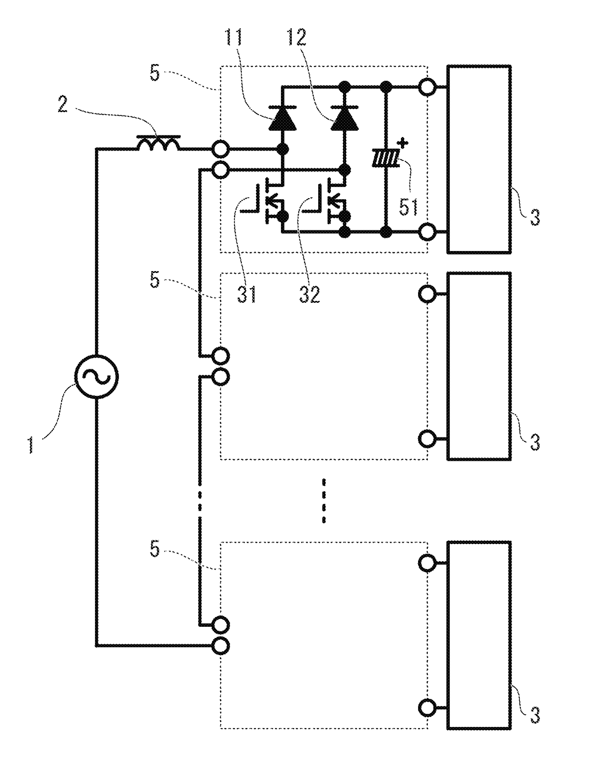
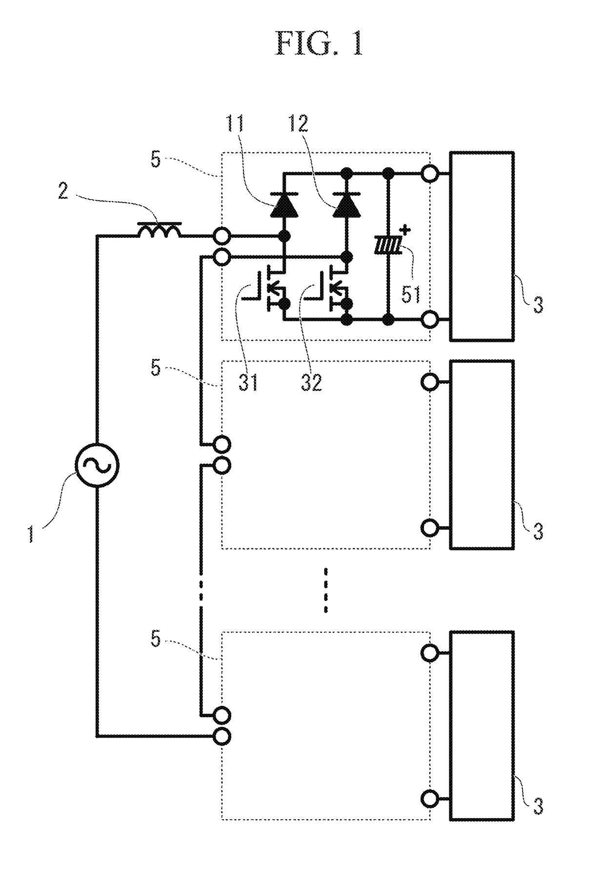
[0070]FIG. 10 shows an example of the present invention where the number of levels n is 4. This converter includes the AC power source 1, the choke 2, the three circuit blocks 5, and the loads 3 each connected to the output terminals of one of the circuit blocks 5.

[0071]Each circuit block 5 includes the first series circuit including the diode 11 and the MOSFET 31, the second series circuit including the diode 12 and the MOSFET 32, and the capacitor 51. The drain of the MOSFET 31 and the anode of the diode 11 are connected, and the drain of the MOSFET 32 and the anode of the diode 12 are connected. One input terminal is connected to the connecting point of the diode 11 and the MOSFET 31, and the other input terminal is connected to the connecting point of the diode 12 and the MO...

example 2

Effect of Example 2

[0082]By the above action, it is possible to, by use of the circuit of the present invention, miniaturize the choke and also miniaturize the noise filter.

Example 3

Configuration of Example 3

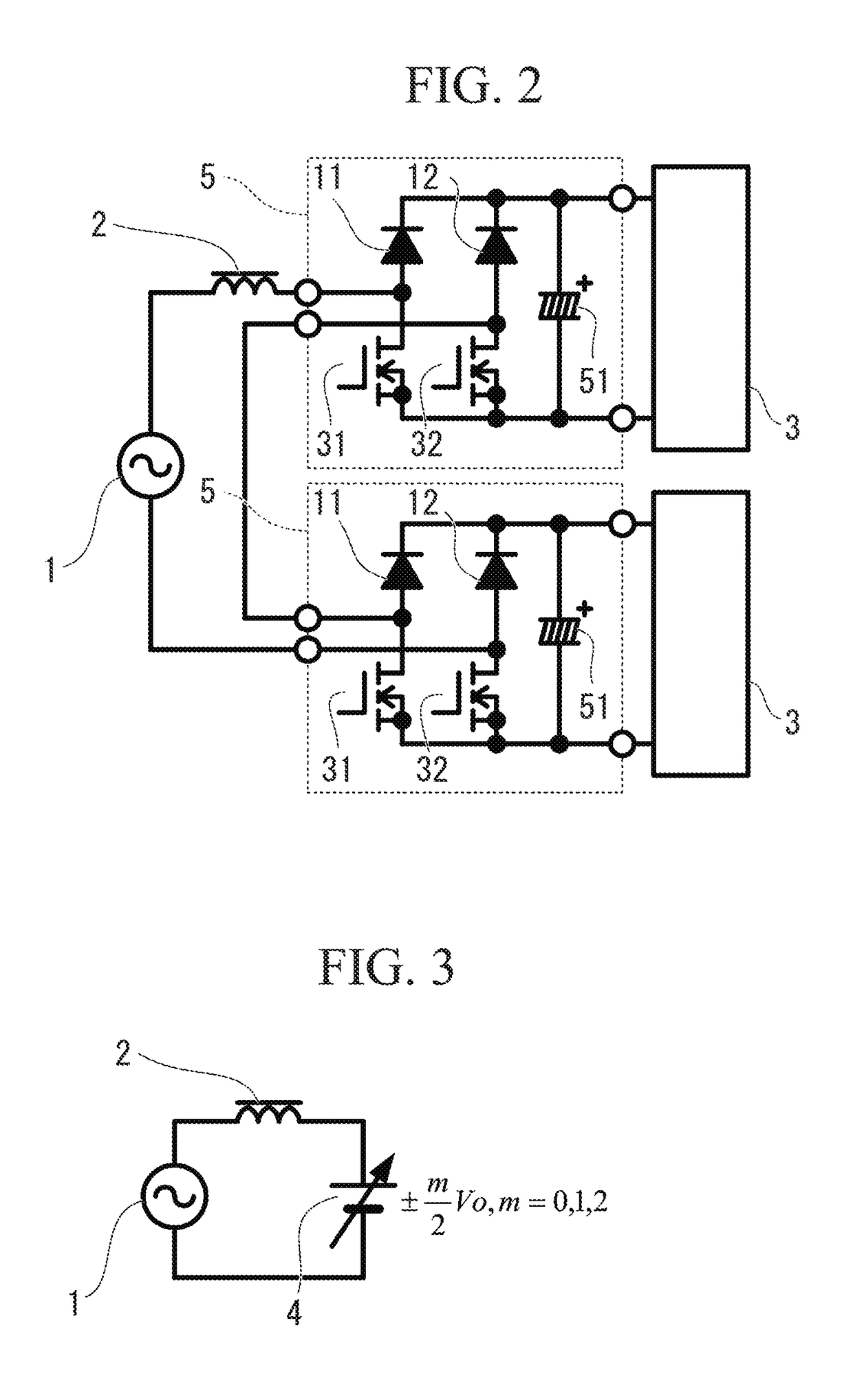
[0083]In Example 3, as the loads for the respective circuit blocks 5 of the circuit shown in FIG. 2, primary sides of full-bridge converters 6 (hereinafter referred to as “converters 6”) are respectively connected, as in a circuit shown in FIG. 12, and outputs of the respective converters 6 are connected to each other and to the load 3.

[0084]In each converter 6, inputs of a bridge circuit including a MOSFET 33, a MOSFET 34, a MOSFET 35, and a MOSFET 36 are connected to the output terminals of each circuit block 5. Outputs of this bridge circuit are connected to a primary winding of a transformer 61. A secondary winding of the transformer 61 is connected to a rectifying circuit including a diode 13, a diode 14, a diode 15, and a diode 16 which are bridged. Outputs of the rectifyi...

example 3

Effect of Example 3

[0087]Thus, the outputs of the respective converters 6 are connected with each other, thereby realizing, as a whole, a single-input single-output isolated converter with the power factor improving function.

[0088]Additionally, each converter 6 is driven while shifting the phases of each converter 6, thereby enabling a reduction in ripple current of the capacitor 52, and thus enabling the miniaturization of the capacitor 52.

[0089]Here, although the example of the full-bridge converter has been taken in the Example 3, a circuit type of the converter 6 is not limited thereto as long as the converter 6 is an isolated converter, thereby still achieving the same effect that, as a whole, a single-input single-output isolated converter with the power factor improving function can be realized by connecting the outputs of the respective converters 6.

[0090]Additionally, although the example of the parallel connection has been taken as the method of connecting the outputs of t...


PUM


Abstract

Provided are a plurality of circuit blocks each including: a first series circuit including a first rectifying element and a first switching element which are connected in series; a second series circuit including a second rectifying element and a second switching element which are connected in series; and a capacitor, wherein output terminals are connected to both ends of the first series circuit, both ends of the second series circuit, and both ends of the capacitor. Input terminals of the respective circuit blocks are connected in series. An AC power source is connected thereto via a choke, thereby solving the problem.

Description

TECHNICAL FIELD[0001]The present invention is an application of the multilevel converter technology to non-isolated power factor improving converters, and particularly relates to cascade multi-cell multilevel converters.BACKGROUND ART[0002]Conventionally, as power factor improving converters, systems using the boost chopper circuits are well known. FIG. 15 shows a circuit diagram of this system. A diode 21, a diode 22, a diode 23, and a diode 24 are bridge-connected, an input thereof is connected to an AC power source 1, and an output thereof is connected to a series circuit including a choke 2 and a MOSFET 37. A series circuit including a diode 25 and a capacitor 54 is connected between a source and a drain of the MOSFET 37, and a load 3 is connected to both ends of the capacitor 54.[0003]Since the power factor improving converter receives an input current obtained by a filter (not shown) removing a high frequency component from a current of the choke 2, a control is performed so t...

Claims


Application Information

Patent Timeline
Patent Type & Authority Applications(United States)
IPC IPC(8): H02M1/42H02M1/08H02M3/335
CPCH02M1/42H02M1/08H02M3/33523H02M1/4225H02M1/4233H02M3/285H02M7/25Y02B70/10Y02P80/10H02M1/007H02M1/0074H02M1/0085
Inventor HAGA, HIROYUKI
Owner SHINDENGEN ELECTRIC MFG CO LTD
Why Eureka
Try Eureka