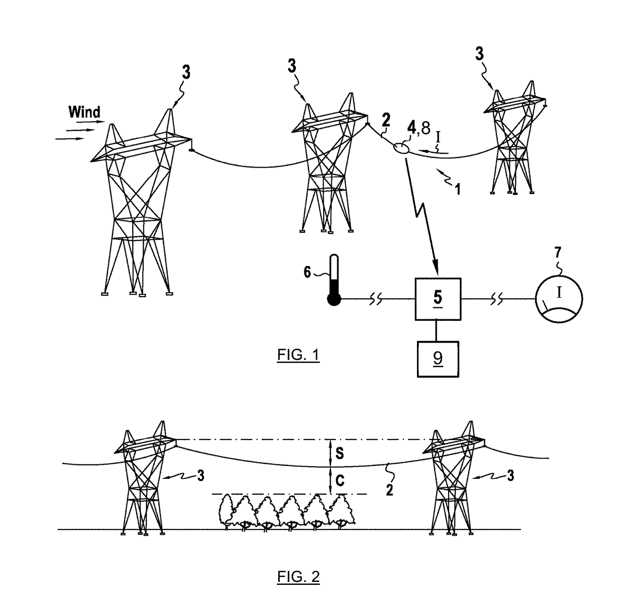
Ice loads can cause significant damage to
electric power transmission networks, especially in combination with wind.
Overhead lines can collapse due to the
mass of ice deposits, but also additional loads in conductors and support structures induced by so-called galloping oscillation can cause significant damage to the structures.
Clashing of conductors and flashovers are the most common problems of transmission lines galloping.
Repeating power interruption caused by flashovers (as flashovers cause circuit breakers to open) obviously reduces the
service quality and can damage the circuit breakers.
And also the conductors can be damaged due to the clashing and flashovers.
Sudden ice shedding generates strong cable motion and high / severe dynamic loads, which can cause severe damages to the transmission lines such as
tower arm failure or even cascading failures of several towers.
Moreover non-uniform
ice accretion on a conductor in adjacent spans results in a longitudinal load at the supports.
Such loading may be created either by a non-uniform ice accretion as a consequence of the line
exposure or owing to ice shedding and can cause severe damage to the
transmission line structures.
One drawback of these methods is that sag conditions are time changing, uncertain and not well-known in practice.
These methods are not always capable of providing a correct picture of the situation.
If for instance a snow or ice load appears on a line span, the calculation from weather to sag will be erroneous.
As
joule heating and weather conditions are sensed by the conductor that determines its
thermal equilibrium / temperature, point measurements of weather and in particular wind variables even taken in close proximity of the line remain inaccurate.
Methods measuring the surface temperature of the phase conductor and methods measuring the angle of the conductor at the pole or at a location along span suffer from the same drawbacks: relation from temperature to sag can be uncertain and / or erroneous in case of icing and / or variations due to icing must be identified in sag variations along time using for example a temperature
estimation.
Methods measuring sag using
image processing and detection of a target installed on the conductor is sensitive to reduction of
visibility induced by meteorological conditions, and in particular in case of ice
fog and freezing
fog.
A drawback of this method is that relation from tension to sag can be uncertain and / or erroneous in case of icing because of unknown apparent conductor weight and / or variations due to icing must be identified in sag variations along time using for example a temperature
estimation.
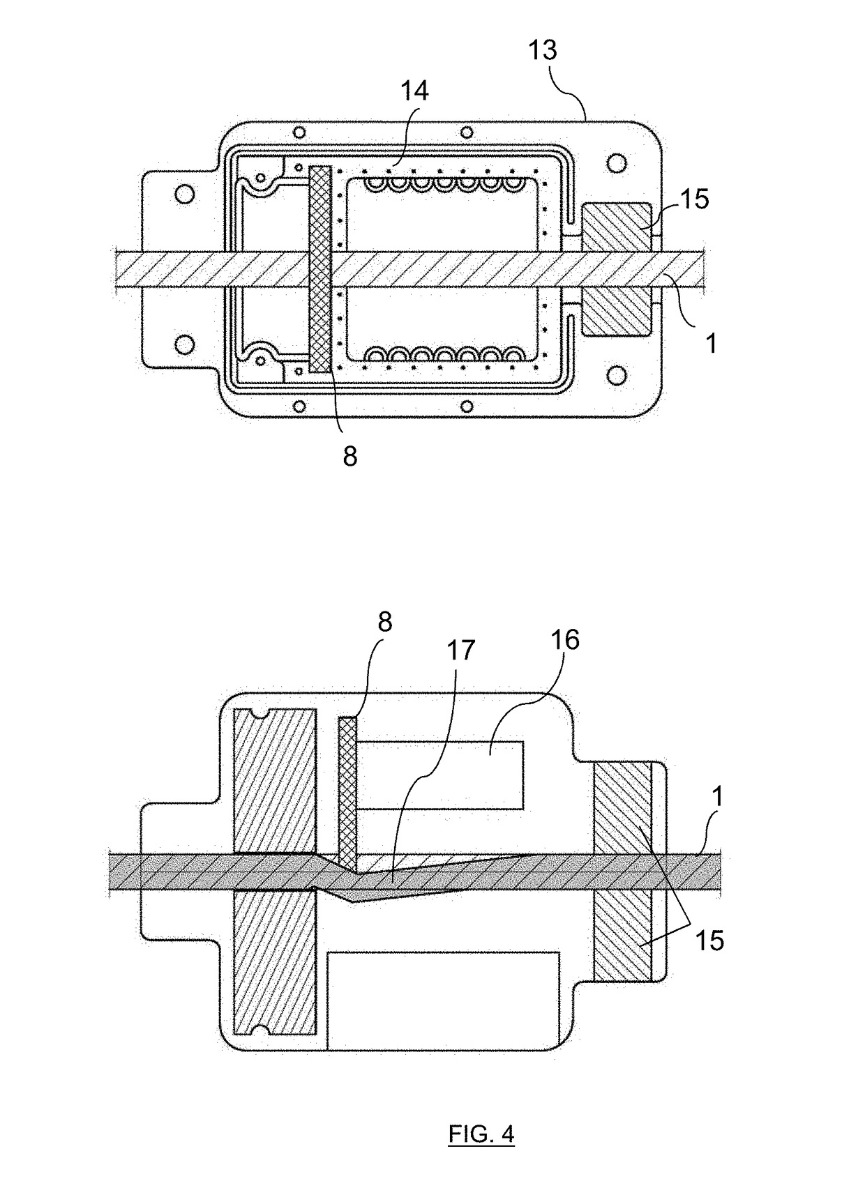
[5] to [8], based on the corresponding method and apparatus detailed in the cited patents, are also available but these sensors are not directly
usable in the domain of power lines domain since no attention was paid therein to
high voltage constraints, as for example need for
electromagnetic shielding of the monitoring
electronics, anti-
corona design, etc.
Regarding ice monitoring of power lines, this tension-based method suffers from previously mentioned drawbacks as the fact that relation from tension to sag can be uncertain and / or erroneous in case of icing because of unknown apparent conductor weight, and / or variations due to icing must be identified in sag (tension) variations along time using for example a temperature
estimation.
Except for vibrations-based sag monitoring detailed is U.S. Pat. No. 8,184,015, for which no
external data such as topological data, conductor (and in particular apparent weight per unit length as explained further) or span data,
weather data, or sagging conditions, etc., are needed for sag monitoring, all other methods exhibit at least some limitations in sag monitoring in case of ice loading periods as ice / snow or other accretion that build up on the conductor will increase the apparent
diameter and weight of the conductor.
As a consequence, the previous methods, except in case of the vibrations-based method, can lead to errors in sag measurement due to atmospheric accretion and these methods eventually must be coupled to weather measurements / information to give data about ice-snow accretion conditions and / or conductor temperature (as conductor temperature is around 0° C. in case of accretion) but there is no information about ice accretion.
The needed weather conditions coming from models and / or weather stations may not be a good estimate of the real weather conditions at conductor location or height, and estimated conductor temperature along the line could be erroneous.
A drawback of such methods however is that the camera must be power supplied close to the power line.
Indirect measurements are inaccurate since sag has to be deduced by algorithms which depend on unavailable and / or
uncertain data (e.g. ice, wind loading) and / or uncertain models.
Sag cannot thus be accurately determined by temperature or indirect measurements in case of atmospheric icing.
This is only a part of the monitoring of the power lines since sag cannot be determined.
A drawback of this
system is that the sensor is not taking into account the current in the power line and the real conductor temperature which can be dramatically different from that of the above-mentioned sensor.

