RFID reading method and RFID reader

a reading method and reader technology, applied in the field of passive wireless sensors, can solve the problems of limited read-out distance, limited lifetime of wireless sensors, and limited lifetim

Active Publication Date: 2017-08-10
METSO OUTOTEC (FINLAND) OY
View PDF0 Cites 9 Cited by
  • Summary
  • Abstract
  • Description
  • Claims
  • Application Information

AI Technical Summary

Benefits of technology

[0030]In an embodiment, the default sensing element comprises a sensing element or a resonator with known temperature dependence, and wherein the RFID reader reads the temperature of the passive RFID tag based on the backscattering modulation frequency of the passive RFID sensor tag having the default sensing element activated, and the RFID reader uses the read temperature to cancel the effect of the temperature variation from the backscattering modulation frequency of the passive RFID sensor tag when other than the default sensing element is activated.

Problems solved by technology

However, wireless sensors also have some drawbacks such as limited lifetime due to battery, limited read-out distance due to attenuation and interference, security issues because of the uncontrollable propagation of the signal and potentially low speed of communication.
However, the battery on board limits the life time and also increases the size and weight.
Due to more complex circuit, the price of an active sensor can be much higher than that of a passive sensor.
RFID tags are equipped with a rewritable memory, which enables the reusability features of RFID tags, but they are not useful for measuring external quantities.
Increased power consumption due to the additional electronics reduces the read-out range significantly (e.g., from 5 m to 0.3 m with an 8-bit A / D converter).
Additional sensor element further increases power consumption.

Method used


Image

  • RFID reading method and RFID reader
  • RFID reading method and RFID reader
  • RFID reading method and RFID reader

Examples


Embodiment Construction

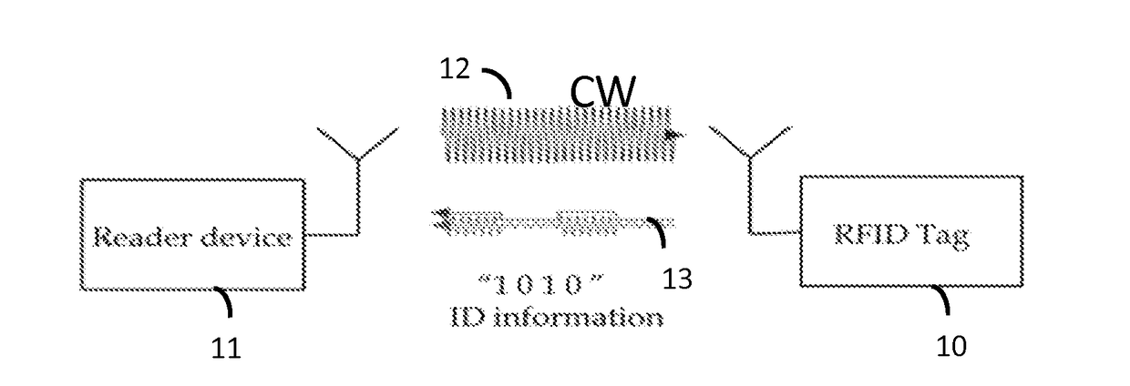
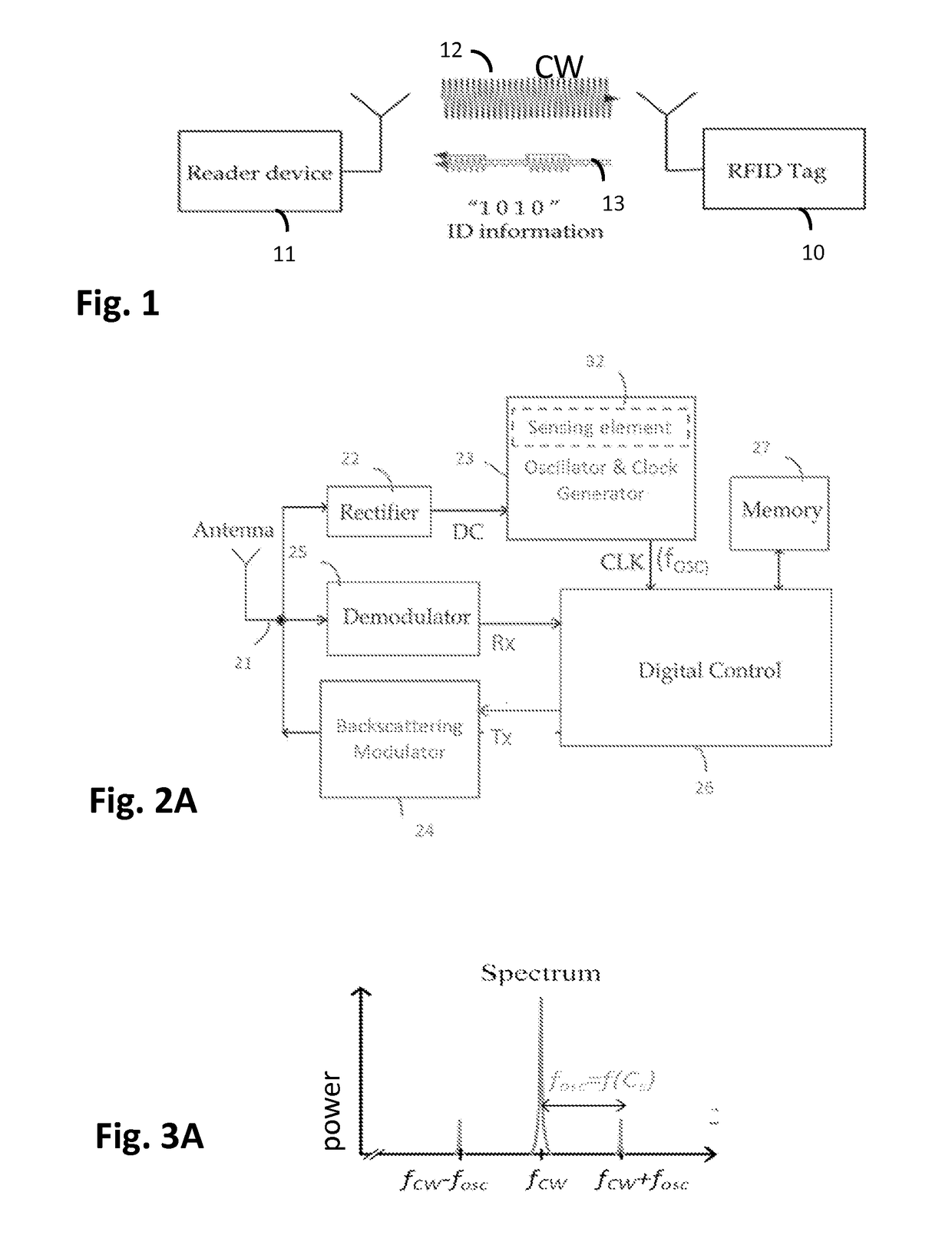
[0050]Referring to FIG. 1, an RFID system typically comprises two basic components: an RFID transponder or tag 10, which is located on the object to be identified or at a measurement point; an RFID interrogator or reader 11, which performs the interrogation of RFID tags. In a passive RFID system the RFID reader 11 supplies the tag 10 with essential power in order for it to perform modulation of the reader's interrogation signal. In the case of RFID sensor tags, in addition to just providing a power source and medium for the RFID tags 10 to operate and transmit data, an RFID reader 11 may perform data transmission, which is implemented, in most cases, as a modulation of the carrier signal, towards the tags 10.

[0051]FIG. 2A shows a functional block diagram illustrating a further example of radio frequency identity (RFID) tag architecture. In the illustrated example the RFID tag 10 may comprise an antenna 21 directly matched to the tag's front end impedance (matching circuit is not sho...


PUM


Abstract

A radio frequency identification (RFID) reader sequentially carries out inventory rounds with passive RFID sensor tags. Each RFID sensor tag has at least one sensing element arranged to sense a predetermined quantity. The reader reads one value of the predetermined quantity based on a backscattering modulation frequency used by the passive RFID sensor tag during each inventory round and releases the RFID sensor tag prior to reading next value of the predetermined quantity based on a backscattering modulation frequency used by the passive RFID sensor tag during a subsequent inventory round. If the passive RFID sensor comprises two or more sensing elements having different sensor characteristics, the reader reads one of the sensing elements of the passive RFID tag during one inventory round and releases the passive RFID sensor tag prior to reading another one of the sensing elements of the passive RFID sensor tag during a subsequent inventory round.

Description

FIELD OF THE INVENTION[0001]The present invention relates to passive wireless sensors, particularly passive radio frequency identification (RFID) sensors, RFID sensor systems, and RFID readers for passive RFID sensor tags.BACKGROUND OF THE INVENTION[0002]Sensor is a device that transforms a measured quantity into a readable format, typically into an electrical signal. Nowadays, there are commercially available sensors virtually for any measurement purpose. According to the connectivity, sensors can be divided into wireless and wired sensors. Wired sensors are connected via wiring harnesses or cable assemblies to a reader device. Wireless sensors can be read without a physical connection to the sensor, and are often realized equipping the sensor with a radio transceiver. The transmitted radio signal is interpreted by a receiver which converts the wireless signal into a desired output. Wireless operation can be beneficial in many applications, where wired connection is difficult for e...

Claims


Application Information

Patent Timeline
Patent Type & Authority Applications(United States)
IPC IPC(8): G06K17/00G06K7/10
CPCG06K7/10366G06K17/0022G06K7/10G08C17/02G06K19/07G06K7/10039G06K19/0716H01L2021/60075G06K7/10009G06K19/0717G06K19/0719G06K19/0723
Inventor NIKUNEN, JOONAVIIKARI, VILLE
Owner METSO OUTOTEC (FINLAND) OY
Why Eureka
Try Eureka