Vehicle aerodynamic apparatus

a technology of aerodynamic apparatus and vehicle, which is applied in the direction of vehicle body, vehicle body streamlining, superstructure subunit, etc., can solve the problems of limiting its applicability in automotive design, and achieve the effect of increasing the efficacy of the jet of air and effective control of the vehicle wak

Active Publication Date: 2017-08-24
JAGUAR LAND ROVER LTD
View PDF1 Cites 14 Cited by
  • Summary
  • Abstract
  • Description
  • Claims
  • Application Information

AI Technical Summary

Benefits of technology

[0029]The first and second duct outlets can be disposed at the rear of the vehicle. The first and second duct outlets can be disposed in a rear-facing surface of the vehicle body. The jets of air output from said first and second duct outlets can be introduced directly into the wake formed behind the vehicle. Thus, at least in certain embodiments, the jets of air do not travel over other sections of the vehicle body, such as the boot (trunk) lid or rear engine compartment cover, before influencing the wake. The rear ducts can more effectively control the vehicle wake.
[0030]The first and secon

Problems solved by technology

However, aesthetic and packaging consideration

Method used


Image

  • Vehicle aerodynamic apparatus
  • Vehicle aerodynamic apparatus
  • Vehicle aerodynamic apparatus

Examples


Embodiment Construction

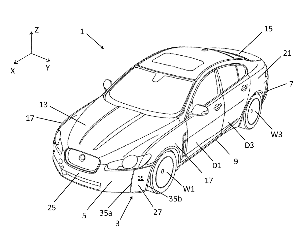
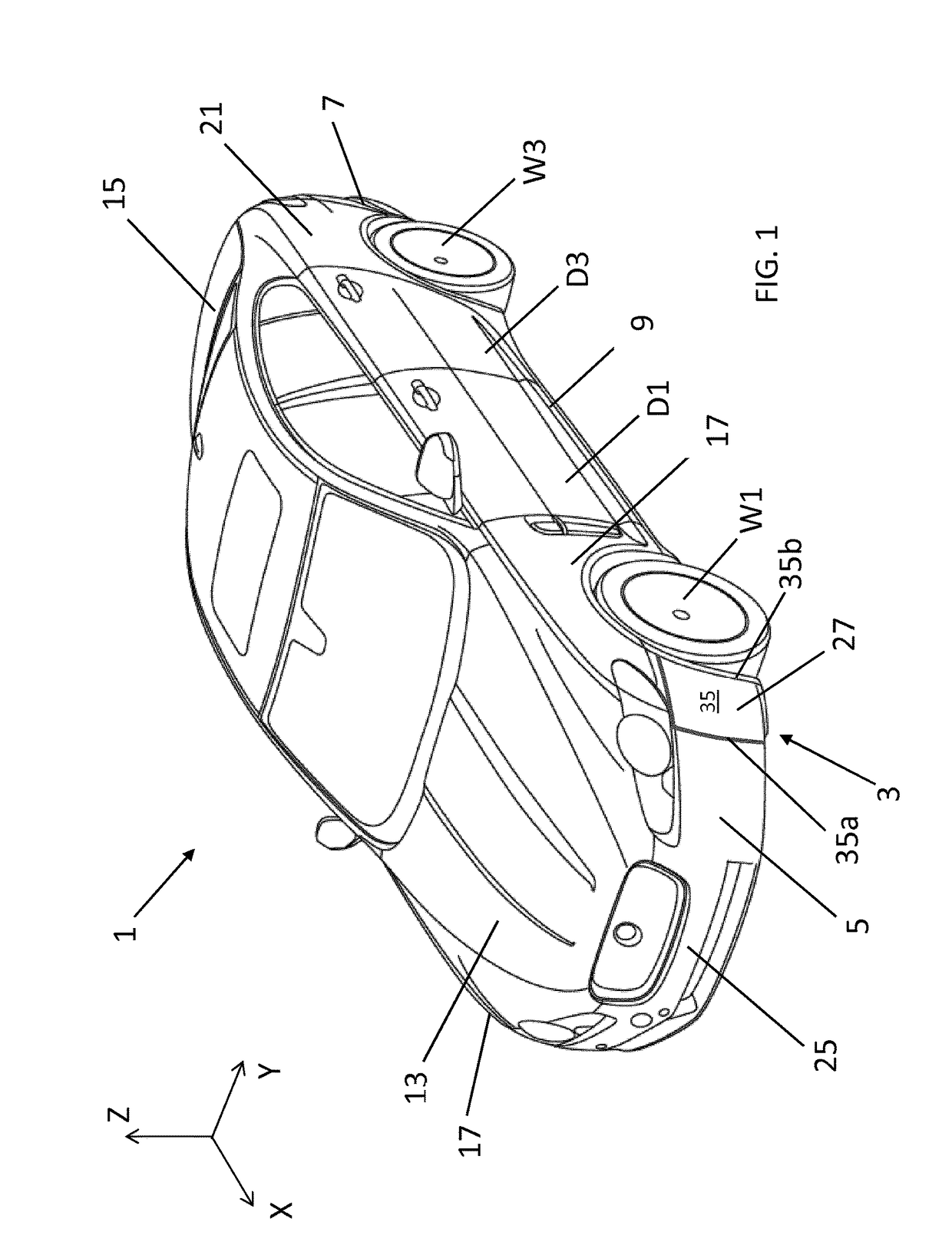
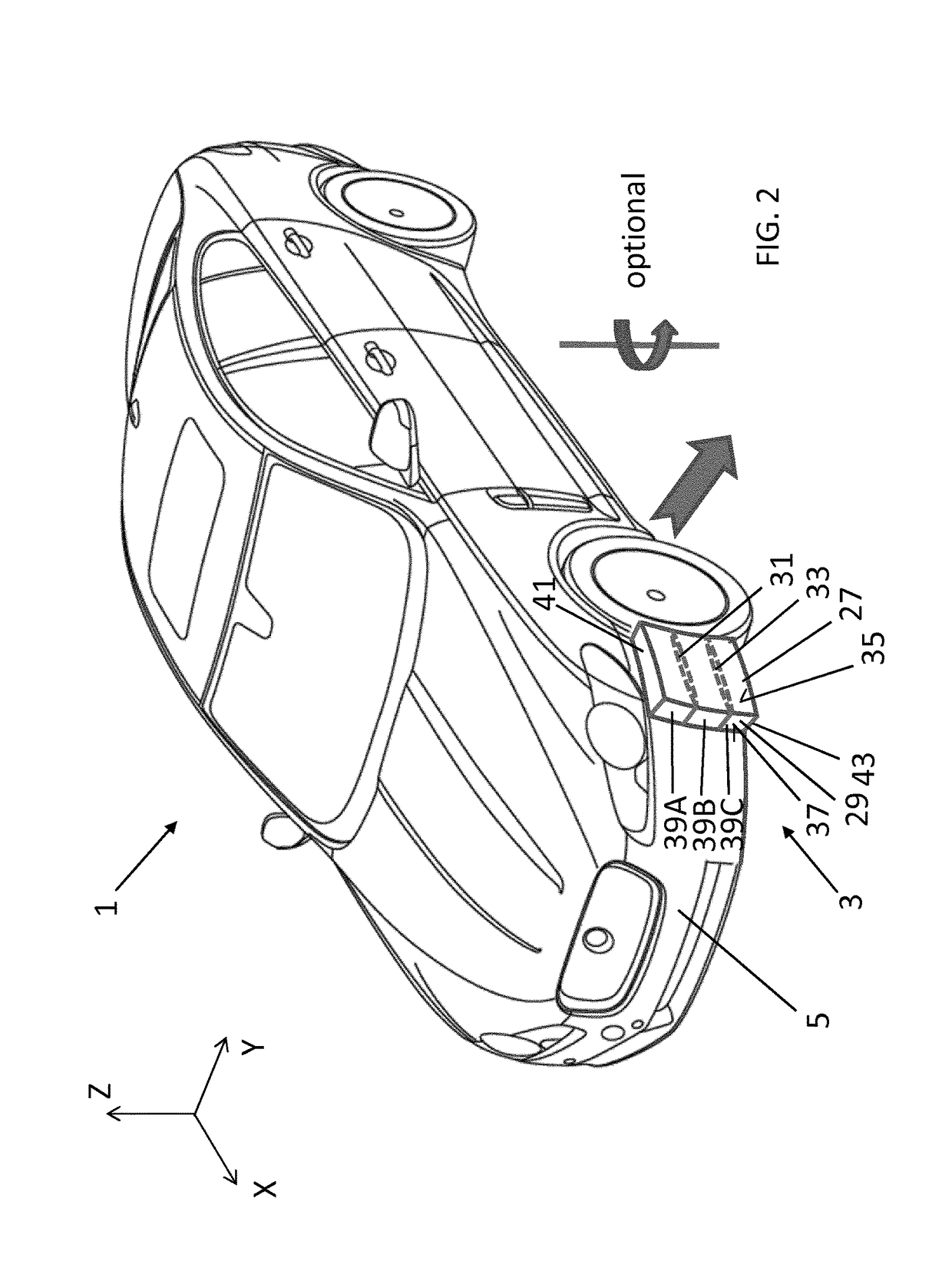
[0064]A vehicle 1 comprising first and second deployable turning-vane assemblies 3 in accordance with an embodiment of the present invention is illustrated in FIGS. 1 and 2. The first and second turning-vane assemblies 3 are provided on the left and right sides respectively of the vehicle 1.

[0065]The first and second turning-vane assemblies 3 are deployable outwardly to modify the planform of the front corners of the vehicle 1 to improve aerodynamic efficiency. The outer surface of each of the first and second turning-vane assemblies 3 is profiled to improve longitudinal airflow along the respective sides of the vehicle 1. In the illustrated arrangement, the vehicle 1 is a motor vehicle having a saloon (sedan) configuration, but the first and second turning-vane assemblies 3 can be employed in other motor vehicle configurations.

[0066]The first and second turning-vane assemblies 3 are described herein with reference to a longitudinal axis (X), a transverse axis (Y) and a vertical axi...


PUM


Abstract

The present application relates to a vehicle (401). A first duct (457) having a first duct inlet (467) and a first duct outlet (469) is provided on a first lateral side of the vehicle (401). A second duct (457) having a second duct inlet (467) and a second duct outlet (469) is provided on a second lateral side of the vehicle (401). The first and second duct inlets (467) are arranged substantially in line with or inset from the respective first and second lateral sides of the vehicle (401). The first and second duct outlets (469) are disposed at or proximal to a rear of the vehicle (401) and arranged, in use, to direct respective first and second jets of air inwardly to control the lateral propagation of a wake formed behind the vehicle (401). Duct sidewalls are formed by surfaces of rear pillars of the vehicle (401).

Description

TECHNICAL FIELD[0001]The present disclosure relates to a vehicle aerodynamic apparatus; to a guide vane assembly; to a guide vane and to a vehicle.BACKGROUND[0002]The drag of the rear facing surfaces of a car (base drag) can account for upwards of 30% of the total drag. ‘Boat tailing’ (a progressive reduction in vehicle width (Y) and / or height (Z) along a longitudinal axis (X) towards the rear of the vehicle) has been a historic countermeasure. This promotes base pressure recovery, reducing drag. However, aesthetic and packaging considerations limit its applicability in automotive design.[0003]US20110000727 discloses air inlet openings formed in vertical fins extending from the longitudinal roof members. The air inlet openings direct air over an outer skin of a rear deck lid and onto a rear air deflection device.[0004]US20120104800 discloses a vehicle having an opening formed between lateral end sections of the windshield and the adjacent A-pillars. The air flows through this gap-sh...

Claims


Application Information

Patent Timeline
IPC IPC(8): B62D35/00B62D37/02B62D25/04B62D35/02
CPCB62D35/005B62D35/007B62D25/04B62D35/02B62D37/02B62D35/008Y02T10/82B62D35/00
Inventor GAYLARD, ADRIANTHOMPSON, CHRISTOPHERTURNER, ROSS
Owner JAGUAR LAND ROVER LTD
Why Eureka
Try Eureka