
Optically pumped semiconductor laser with mode tracking

a technology of optical pumping and semiconductor lasers, applied in the direction of laser details, electrical equipment, active medium materials, etc., can solve the problems of short period of instability, inability to control the cw process, and instantaneous change in output power

Active Publication Date: 2017-08-24
COHERENT LASERSYST
View PDF2 Cites 0 Cited by
  • Summary
  • Abstract
  • Description
  • Claims
  • Application Information

AI Technical Summary

Benefits of technology

The present invention is related to a laser apparatus that includes a laser resonator with a gain-structure that allows for the production of different frequencies of light. The apparatus includes an optically nonlinear crystal which is located in the laser resonator and is responsible for converting the light into different frequencies. The nonlinear crystal has a limited acceptance bandwidth which needs to be carefully controlled. The apparatus also includes a detector that monitors the light that is reflected from a birefringent filter. This allows for the accurate monitoring of light that is at a specific frequency. By controlling the temperature of the nonlinear crystal, the apparatus can successfully achieve the desired frequency conversion. Overall, this invention provides a more efficient and accurate way for producing different frequencies of light.

Problems solved by technology

Unfortunately, the pass-bandwidth of such a birefringent filter is still sufficiently broad that in a resonator having a length of about 70 millimeters (mm) there may be several possible oscillating modes (frequencies).
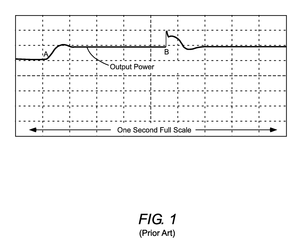
At the instant of the mode hop there is an abrupt (essentially instantaneous) change in output power followed by a brief period of instability.
In applications such as inspection of semiconductor wafers such an interruption of the CW process may be intolerable, even if the wavelength change due to the mode-hop is tolerable.

Method used


Image

  • Optically pumped semiconductor laser with mode tracking
  • Optically pumped semiconductor laser with mode tracking
  • Optically pumped semiconductor laser with mode tracking

Examples


Embodiment Construction

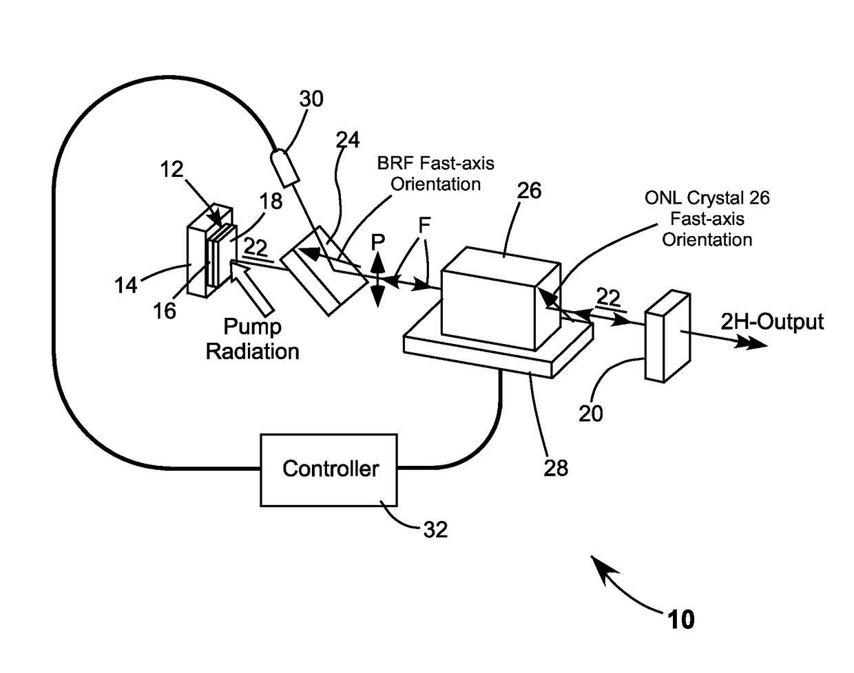
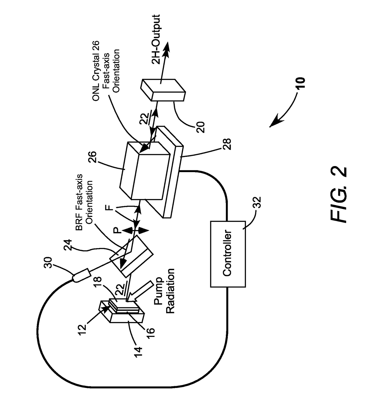
[0017]Referring now to the drawings, wherein like components are designated by like reference numerals, FIG. 2 schematically illustrates a preferred embodiment 10 of an intra-cavity frequency-doubled OPS-laser in accordance with the present invention. Laser 10 includes an OPS-chip 12 mounted on a substrate or heat-sink 14. The OPS-chip includes a mirror-structure 16 surmounted by a multilayer gain-structure 18. Mirror-structure 18 and an end-minor 20 form a laser-resonator 22.

[0018]Pump-radiation from a diode-laser bar or stack thereof (not shown) is directed onto gain-structure 18 causing fundamental-wavelength (fundamental frequency) laser-radiation to circulate in laser-resonator 22 as indicated by arrows F. A birefringent filter (BRF) provides coarse filtering for selection of the fundamental wavelength and establishes the polarization orientation of the circulating fundamental-wavelength radiation as indicated in FIG. 2 by arrows P. The fast-axis orientation of the BRF is at 45...


PUM


Abstract

An intra-cavity doubled OPS-laser has a laser-resonator including a birefringent filter (BRF) for coarse wavelength-selection, and an optically nonlinear (ONL) crystal arranged for type-II frequency-doubling and fine wavelength-selection. Laser-radiation circulates in the laser-resonator at one of a range of fundamental wavelengths dependent on the resonator length. The ONL crystal has a transmission peak-wavelength dependent on the crystal temperature. Reflection of circulating radiation from the BRF is monitored. The reflection is at a minimum when the ONL crystal transmission-peak wavelength is at the circulating radiation wavelength. The temperature of the ONL crystal is selectively varied to maintain the monitored reflection at about a minimum.

Description

TECHNICAL FIELD OF THE INVENTION[0001]The present invention relates in general to external cavity optically pumped semiconductor (OPS) lasers. The invention relates in particular to intra-cavity frequency converted OPS lasers operating in a single longitudinal mode.DISCUSSION OF BACKGROUND ART[0002]Intra-cavity frequency converted (frequency doubled) OPS-lasers can provide several Watts (W) of continuous wave (CW) radiation output at visible (green) wavelengths while operating in a single longitudinal mode. The green, single-mode output wavelength can be converted to a wavelength in the ultraviolet (UV) region of the electromagnetic spectrum by further frequency multiplication in an optically non-linear crystal outside the OPS laser cavity (laser-resonator).[0003]By way of example, an OPS-laser having a fundamental lasing wavelength of about 1064 nanometers (nm) can be frequency-doubled by an intra-cavity optically nonlinear crystal to provide output radiation having a wavelength of...

Claims


Application Information

Patent Timeline
Patent Type & Authority Applications(United States)
IPC IPC(8): H01S3/109H01S3/13H01S3/10H01S3/16H01S3/091H01S3/102
CPCH01S3/109H01S3/091H01S3/1305H01S3/10061H01S3/1628H01S3/1028H01S5/02453H01S5/041H01S5/141H01S3/08036H01S3/08054H01S3/136H01S5/02446H01S5/18383
Inventor KANNENGIESSER, CHRISTIAN
Owner COHERENT LASERSYST
Learn More