
Method of Generating and Distributing a Second Fuel for an Internal Combustion Engine

a technology of internal combustion engine and fuel economy, which is applied in the direction of combustion-air/fuel-air treatment, machines/engines, fuel intakes, etc., can solve the problems of unnecessary loss of fuel efficiency and increase in pollution, so as to improve the fuel economy and improve the performance of an internal combustion engine

Active Publication Date: 2017-09-07
HYTECH POWER LLC
View PDF16 Cites 18 Cited by
  • Summary
  • Abstract
  • Description
  • Claims
  • Application Information

AI Technical Summary

Benefits of technology

The patent describes a method of improving the performance of an internal combustion engine by injecting a second fuel made by electrolysis of water and one or more other substances into the engine's intake tract. The electrolysis is done in a tank with the help of an electrolysis cell and electrical power. The generated gas mixture is stored at high pressure and then released as needed. The amount of gas injected can be controlled by a controller that receives signals from sensors and makes decisions to control actuators. The method is particularly useful for engines with a large number of cylinders. The technical effect is improved engine performance through the use of a novel second fuel made from electrolysis.

Problems solved by technology

An attributable amount of emissions created by internal combustion engines is a result of the internal combustion engines failure to convert all of the energy available in the hydrocarbon fuel (e.g., gasoline and / or diesel fuel).
This incomplete conversion is often a result of what is commonly referred to as incomplete combustion of the fuel.
Incomplete combustion results in an unnecessary loss of fuel efficiency and an increase in pollution.

Method used


Image

  • Method of Generating and Distributing a Second Fuel for an Internal Combustion Engine
  • Method of Generating and Distributing a Second Fuel for an Internal Combustion Engine
  • Method of Generating and Distributing a Second Fuel for an Internal Combustion Engine

Examples


example 1

[0176]A series of electrolysis cells were studied with different plates. In one cell, uncoated stainless steel plates were used and in a second cell platinum-coated stainless steel plates were used. The electrolyte concentration, of potassium carbonate in water, was adjusted in the cell with uncoated plates such that the current draw was essentially identical. All other conditions we essentially identical. The following table reports the results.

TABLE 1Performance FeatureUncoated versus Coated PlatesElectrolyteUncoated plates required approximately 3 timesConcentrationgreater concentration.HHO GasUncoated plates produced approximately 50% lessProductionHHO gas.Current DrawAfter 4 hours of testing, the cells with uncoatedplates had a noticeably lower electrolyte levelresulting in lower current draw.Experimental Note:Iridium-coated plates performed similar to platinum coated plates

example 2

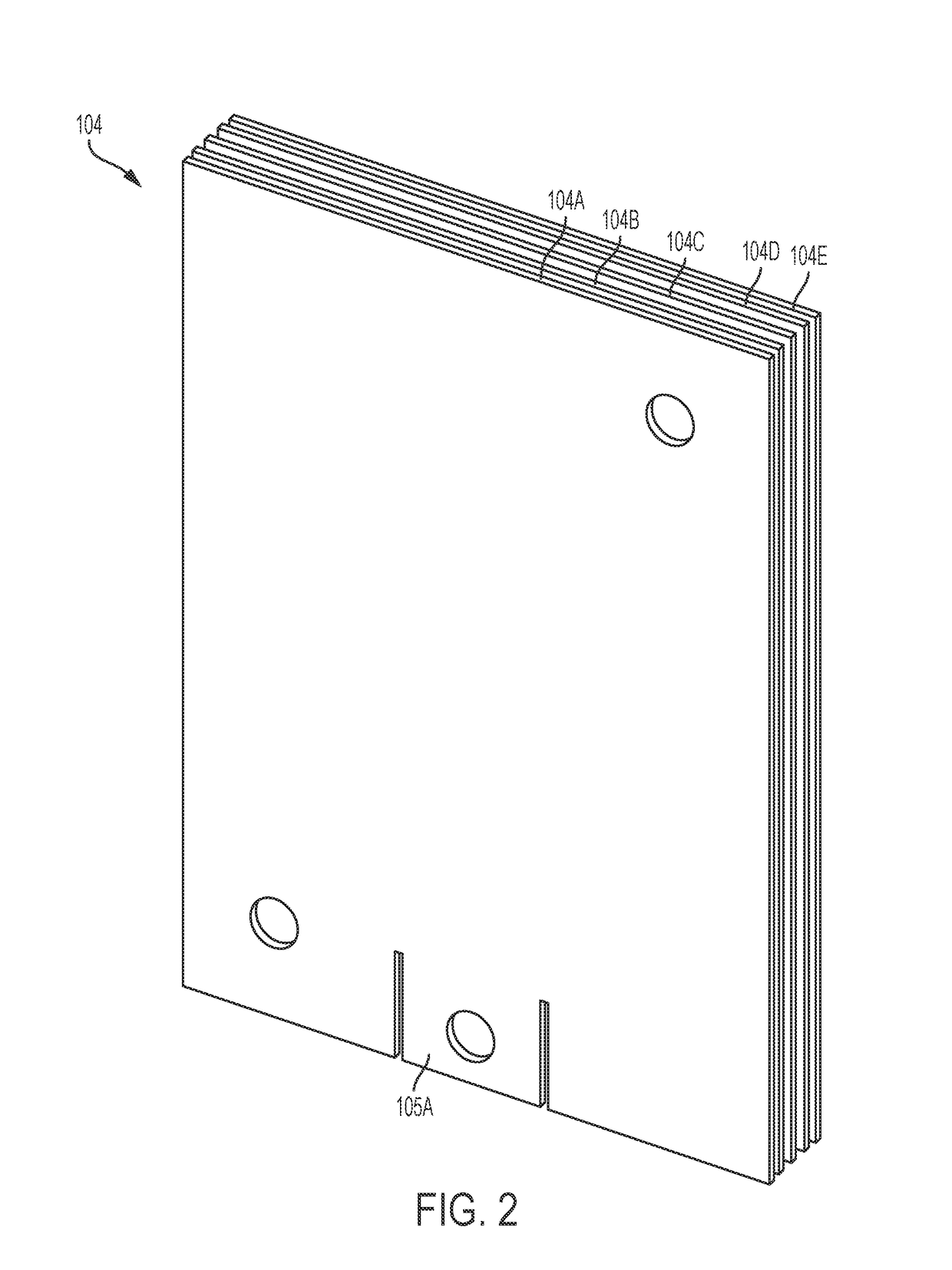
[0177]A series of electrolysis cells were studied with different plates. In a first cell, 7 platinum coated stainless steel plates were used and in a second cell 5 platinum coated stainless steel plates were used. The current draw was kept essentially the same for both cells during the test procedure, by adjusting the concentration of the electrolyte in the 7-plate cell to almost twice the concentration of the 5-plate cell. All other conditions were essentially identical. The following table reports the results.

TABLE 2Performance Feature5 Plates Versus 7 PlatesHHO Gas Production5 plates produced 20-25% more HHO gas.


PUM

PropertyMeasurementUnit
temperatureaaaaaaaaaa
pressureaaaaaaaaaa
pressureaaaaaaaaaa

Abstract

Apparatuses, systems, and methods are disclosed to produce HHO gas in a pressure-resistant container for use in an internal combustion engine to increase fuel efficiency and / or reduce emissions, for example by introducing the HHO gas to one or more air intake ports of the engine.

Description

CROSS-REFERENCE TO RELATED APPLICATIONS[0001]This application claims the benefit of U.S. Provisional Application No. 62 / 304,935, filed Mar. 7, 2016. The foregoing related application, in its entirety, is incorporated herein by reference.FIELD OF THE INVENTION[0002]This disclosure relates to systems and methods for generating HHO gas (a gas resulting from electrolysis of an aquous electrolyte solution) and for distributing and delivering the same about internal combustion engines. In particular, the systems and methods of this disclosure relate to second fuel (the HHO gas) injected in proximity to the engine intake valve or valves. In certain embodiments, for example, the injection system for the second fuel may comprise a multi-point, variable injection system. In certain embodiments, for example, the internal combustion engine may be a spark ignition engine or a compression ignition engine.BACKGROUND OF THE INVENTION[0003]Worldwide emissions, stemming primarily from the burning of ...

Claims


Application Information

Patent Timeline
Patent Type & Authority Applications(United States)
IPC IPC(8): F02B43/12F02M43/04C25B15/08F02M35/10C25B1/06C25B9/06F02M21/02F02M35/104C25B9/17
CPCF02B43/12F02M21/0221F02M21/0239F02M21/0248F02M21/0287F02M43/04F02B2043/106F02M35/10255F02M35/10216F02M35/10177C25B1/06C25B9/06C25B15/08F02M35/104F02B43/10C25B1/04C25B11/00C25B9/17Y02T10/30Y02E60/36C25B1/044Y02T10/12
Inventor JOHNSON, EVAN CHARLESFILKINS, ADAM ANTHONYDEMING, HERBERT DANIELDEAN, HENRY WHITEJENNINGS, PHILLIP EDWARD
Owner HYTECH POWER LLC
Learn More