Thermal pattern sensor with bolometers under capsule(s)
Inactive Publication Date: 2017-09-07
COMMISSARIAT A LENERGIE ATOMIQUE ET AUX ENERGIES ALTERNATIVES
View PDF0 Cites 5 Cited by
- Summary
- Abstract
- Description
- Claims
- Application Information
AI Technical Summary
Benefits of technology
The patent describes a sensor that can create a two-dimensional map of heat transfer between an object and the sensor. This helps to determine the thermal mass of the object. The sensor is protected from external mechanical stress through a capsule, and its insulation ensures good insulation and strength. The object to be imaged is not directly placed on the bolometric plates but on the contact surface above the capsule, which protects them from compressive stress. This allows for accurate and safe imaging.
Problems solved by technology
After a very short time interval, the temperatures stabilise and the image obtained is insufficiently contrasted.
Despite the potential presence of the insulating material, heat is transmitted rapidly from the VOx layer to the substrate, which adversely affects the contrast of the image obtained.
Method used
View moreImage
Smart ImageViewing Examples
Examples
first embodiment
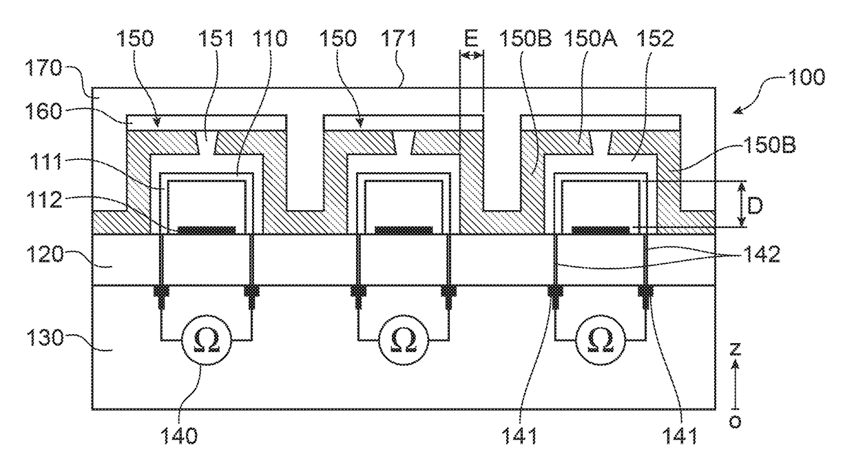
[0055]FIG. 1 illustrates a print sensor according to the invention, according to a sectional view;
second embodiment
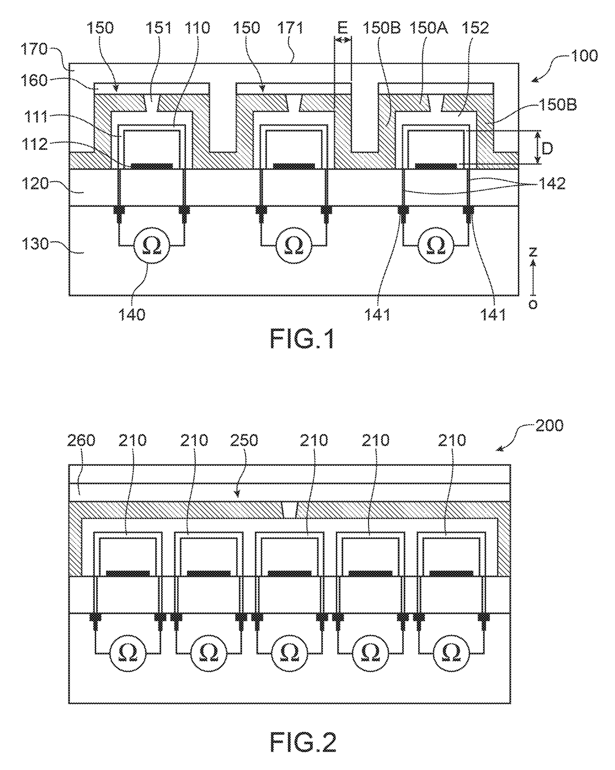
[0056]FIG. 2 illustrates a print sensor according to the invention, according to a sectional view;
third embodiment
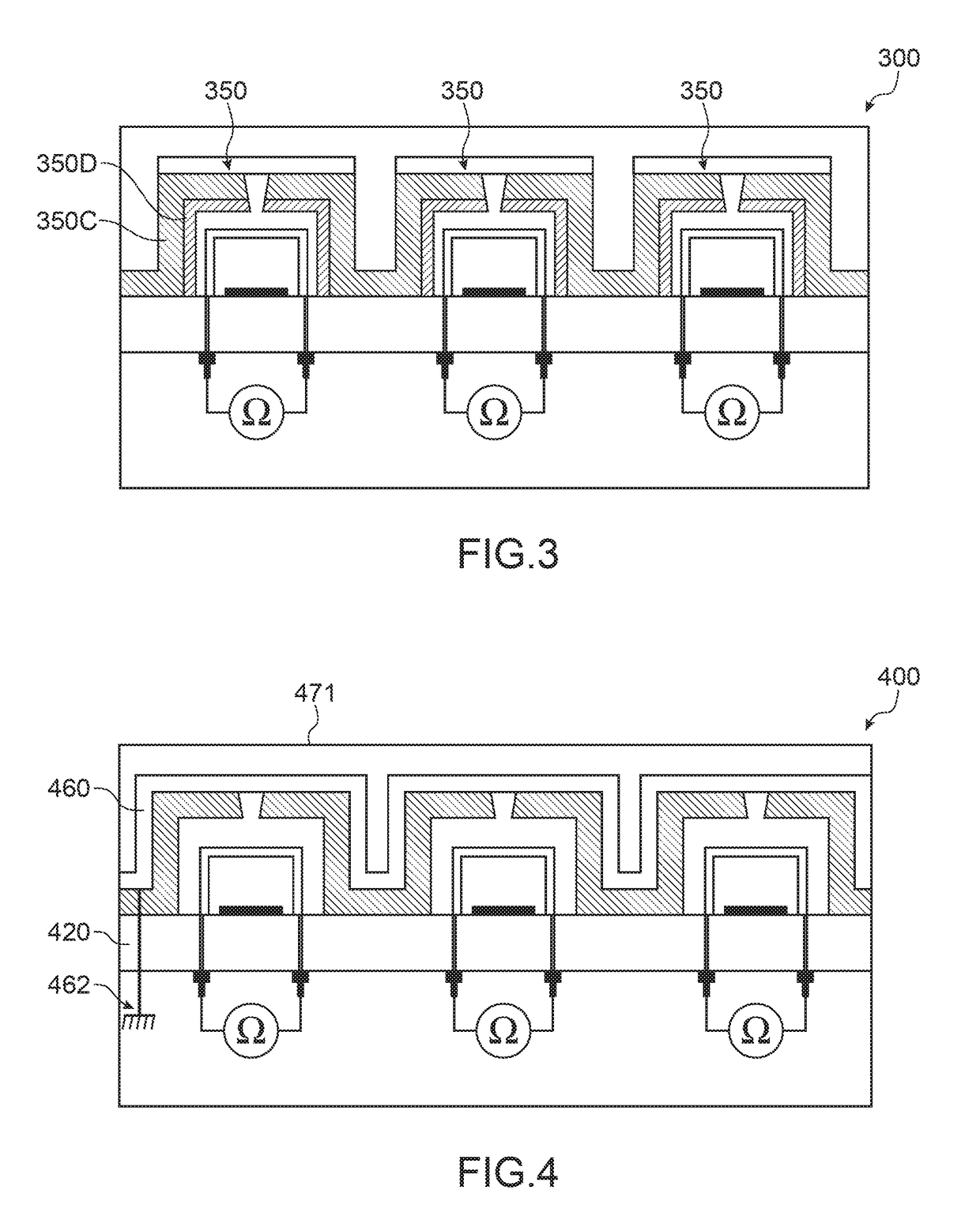
[0057]FIG. 3 illustrates a print sensor according to the invention, according to a sectional view;
Login to View More PUM
 Abstract
A sensor of thermal patterns of an object, of papillary print sensor type, including a contact surface to apply the object thereon. The sensor includes at least one capsule sealed under vacuum, arranged between a substrate and the contact surface, suited to exchanging heat with the object and to emitting electromagnetic radiation as a function of its temperature; inside each capsule, at least one bolometric plate, to convert incident electromagnetic radiation into heat; at least one optical filter, to stop electromagnetic radiation in the infrared, each capsule being covered by an optical filter; with reading the electrical resistances of the bolometric plates. Such a print sensor offers both good insulation between the substrate and the sensitive elements, and good mechanical strength.
Description
TECHNICAL FIELD[0001]The invention relates to the field of thermal pattern sensors or detectors, or sensors of the thermal print of an object, for imaging the thermal patterns of an object, designated object to image.[0002]Such sensors measure a two-dimensional distribution of the thermal mass of an object with which they are in direct physical contact, and even its thermal capacity and / or its thermal conductivity.[0003]They form transducers of a temporal variation in temperature, into a difference in potentials or currents.[0004]Such a sensor may form a mass spectrometer type analysis apparatus, or flowmeter (by heating the object at one spot and measuring up to where the heat propagates). It may form in particular measuring means at various depths in an object, by varying the power injected to heat the object, and the measuring times.[0005]It may also form a papillary print sensor, for imaging a print linked to the particular folds of the skin, in particular a finger print, but al...
Claims
Login to View More Application Information
Patent Timeline
 IPC IPC(8): G01J5/20H01L27/146
CPCH01L27/14621G01J5/20G01J5/0802G06V40/1306G01J5/023G01J5/34
Inventor BECKER, SEBASTIENMAINGUET, JEAN-FRANCOIS
Owner COMMISSARIAT A LENERGIE ATOMIQUE ET AUX ENERGIES ALTERNATIVES
Features
- R&D
- Intellectual Property
- Life Sciences
- Materials
- Tech Scout
- Unparalleled Data Quality
- Higher Quality Content
- 60% Fewer Hallucinations
Learn More Browse by: Latest US Patents, China's latest patents, Technical Efficacy Thesaurus, Application Domain, Technology Topic, Popular Technical Reports.
© 2025 PatSnap. All rights reserved.Legal|Privacy policy|Modern Slavery Act Transparency Statement|Sitemap|About US| Contact US: help@patsnap.com


