Head mounted display using spatial light modulator to move the viewing zone

a technology of spatial light modulator and head mounted display, which is applied in the field of wearable displays, can solve the problems of large space between the eyepiece and the display module, large eyepiece and display module space, and large device bulk, so as to achieve more durable and more resistant to shocks

Inactive Publication Date: 2017-09-07
SHARP KK
View PDF21 Cites 43 Cited by
  • Summary
  • Abstract
  • Description
  • Claims
  • Application Information

AI Technical Summary

Benefits of technology

[0017]Because the viewing zone (exit pupil) of the system is steered by an SLM instead of mechanical mirrors, no intermediate images of the viewing zone (exit pupil) are formed, eliminating the need of bulky relay optics or large space for viewing zone steering mirrors. SLMs are also more durable than large mechanical mirrors and are more resistant to shocks—something wearable devices are frequently subjected to. In add

Problems solved by technology

However, since the unaided human eye cannot accommodate for images closer than a certain distance from the eye, eye piece lenses are required to re-image the display module such that the display appears to be at a comfortable viewing distance from the user.
Such optical configuration requires lots of space between the eye piece and the display module.
Furthermore, complex lenses are needed if the HMD needs to display images with high quality and wide field of view.
These lenses often make the device very bulky to wear.
This method leads to images with low effective resolution.
However, the stringent requirement to align the scanning mirror through the eye's pupil means that it is very difficult to fabricate an HMD that fits different anthropometric variations.
These systems suffer from a number of problems.
Firstly, the mechanical mirror used to steer the eye points either needs to be large, or relay optics will be required to form intermediate images of t

Method used


Image

  • Head mounted display using spatial light modulator to move the viewing zone
  • Head mounted display using spatial light modulator to move the viewing zone
  • Head mounted display using spatial light modulator to move the viewing zone

Examples


1st embodiment

1st Embodiment

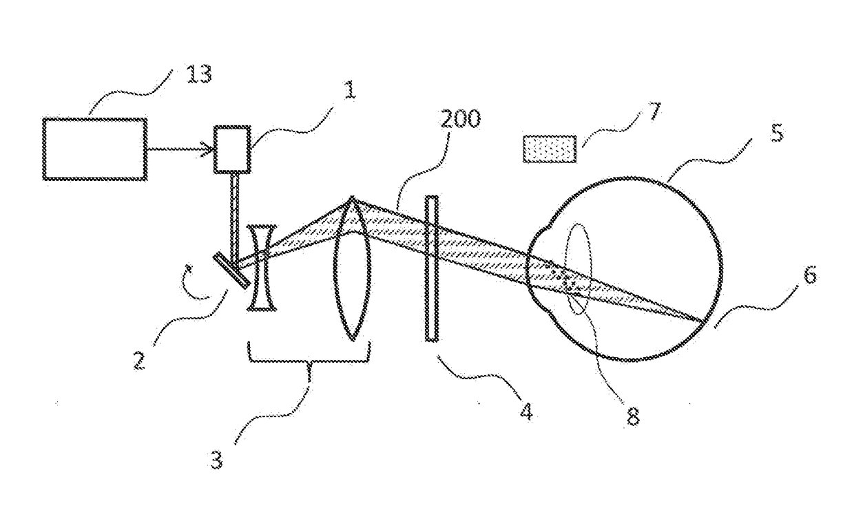
[0095]The first embodiment of this invention is shown in FIGS. 1-3. The device is a head mounted display. In exemplary embodiments, the head mount display is a wearable device that includes a light source and a display unit. The display unit includes an image engine that controls the light source to generate image content for display, and a plurality of optical elements configured to direct the image content into a viewing zone. An eye monitor measures information pertaining to an eye configuration of a user wearing the wearable device, wherein the image content is visible to the user when the eye is aligned with respect to the viewing zone. A spatial light modulator (SLM) is configured to move a position of the viewing zone based on the eye configuration information measured by the eye monitor.

[0096]FIG. 1 shows the device's main components at one moment in time. This embodiment's system includes a laser 1, scanning mirror 2, several fixed lenses 3, a spatial light mo...

2nd embodiment

2nd Embodiment

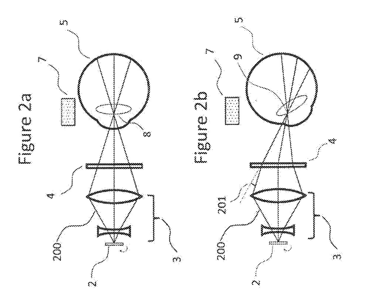
[0106]The second embodiment is shown in FIGS. 4a-c, where lens array 20 including a plurality of lenslets is added to the system. FIG. 4a shows the HMD functioning as a multiple eye point retinal scanning system. Each lenslet from the lens array creates a separate eye point (22a-c) unshifted by the SLM 21 in FIG. 4a. In other words, each lenslet in the array directs the image content into a separate eyepoint corresponding to a respective viewing zone. An image will be visible as long as the user's pupil is placed at or aligned with one of these eye points. The inclusion of the SLM 21 not only makes the system capable of moving a single eye point, but could also change the position of individual eye points.

[0107]When combined with eye configuration information obtained from the eye monitor, the separation between these eye points can be varied to accommodate for the varying pupil size of users such that only one eye point enters the eye at any time. For example, if a us...

3rd embodiment

3rd Embodiment

[0115]FIGS. 6a-b shows the third embodiment where an SLM is employed in a light field HMD. FIG. 6a shows a light field HMD which includes an SLM 32 and a display unit. The display unit further includes an image engine 30 and fixed optics 31. The display engine 30 is an OLED screen but may also be any pixelated image display panels such as an LCD display. The fixed optics may be configured as a lens array. The light field HMD has a finite viewing zone 207a where the full image is only viewable when the eye is placed within this zone. Depending on the ergonomics of the user, it is likely that his eyes will not be placed in the optimal position of the zone. Hence the SLM can be used to change the location or distance from the image panel (206a-b) and size (207a-b) of this viewing zone depending on the eye configuration information obtained from the eye monitor.


PUM


Abstract

A wearable device includes a light source and a display unit. The display unit includes an image engine that controls the light source to generate image content for display, and a plurality of optical elements that direct the image content into a viewing zone. An eye monitor measures information pertaining to an eye configuration of a user wearing the wearable device, and the image content is visible to the user when the eye is aligned with respect to the viewing zone. A spatial light modulator (SLM) moves a position of the viewing zone based on the eye configuration information measured by the eye monitor. The eye monitor measures pupil size of the user, and the optical elements direct the image content into the viewing zone that is smaller in at least one dimension than twice the measured pupil size. The light source may include a micro-electro-mechanical systems (MEMS) scanning mirror.

Description

TECHNICAL FIELD[0001]The invention has application within the field of wearable displays. It is used for achieving a light weight design in head mounted displays.BACKGROUND ART[0002]Head-Mounted-Displays (HMD) is a type of device with increasing popularity within the consumer electronics industry. HMDs, along with similar devices such as helmet-mounted displays, smart glasses, and virtual reality headsets, allow users to wear a display device such that the hardware remains fixed to their heads regardless of the person's movement.[0003]When combined with environmental sensors such as cameras, accelerometers, gyroscopes, compasses, and light meters, HMDs can provide users with experiences in virtual reality and augmented reality. Virtual reality allows a user to be completely submerged into a virtual world where everything the user sees comes from the display device. On the other hand, devices that provide augmented reality allow users to optically see the environment. Images generate...

Claims


Application Information

Patent Timeline
IPC IPC(8): G02B27/01G06F3/01
CPCG02B27/0172G02B2027/0187G06F3/013G02B27/0179G02B27/017G02B2027/0127G02B2027/0147
Inventor TAM, KA HOMONTGOMERY, DAVID JAMESSMEETON, TIM MICHAEL
Owner SHARP KK
Why Eureka
Try Eureka