System and method for robotic thermal treatment by heat induction

Inactive Publication Date: 2017-09-14
HYDRO QUEBEC CORP
View PDF0 Cites 3 Cited by
  • Summary
  • Abstract
  • Description
  • Claims
  • Application Information

AI Technical Summary

Benefits of technology

[0003]To restore the mechanical properties and reduce the internal stresses induced during welding with a homogeneous wire, manufacturers place, once the wheel is completed, the entire piece in a furnace of very large size. Th

Problems solved by technology

The wheels are aging and cracks resulting from fatigue loading appear in several facilities.
The problem is even aggravated as the properties of the base material around the area where the crack has spread have not been able to withstand the passage of time.
In summary, the weakening of the wheel due to the current repair process generates a recurrin

Method used


Image

  • System and method for robotic thermal treatment by heat induction
  • System and method for robotic thermal treatment by heat induction
  • System and method for robotic thermal treatment by heat induction

Examples


Embodiment Construction

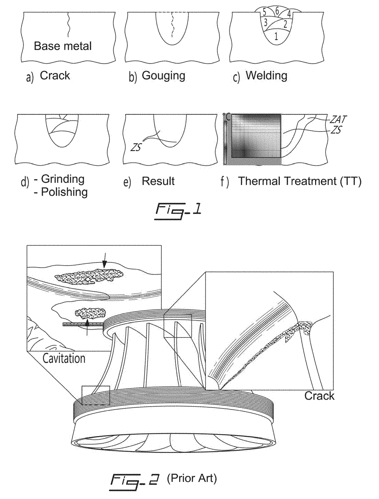
[0045]Referring to FIG. 1, there is illustrated the steps of repair of a crack in a base piece of metal, according to a preferred embodiment of the present invention. The repair comprises the following steps of: a) detecting a crack; b) performing a gouging and / or machining around the crack; c) welding after the gouging and / or machining; d) grinding and / or polishing after the welding; e) inspecting the result of the welded zone (ZS); f) performing a thermal treatment of the welded zone (ZS) that extends to a heat affected zone (ZAT) if necessary. A thermal treatment (TT) may be performed manually using a heater or a torch. However, the inventors have found that it is extremely difficult, if not impossible, to maintain a relatively uniform heating temperature across the entire surface of the welded zone (ZS) manually.

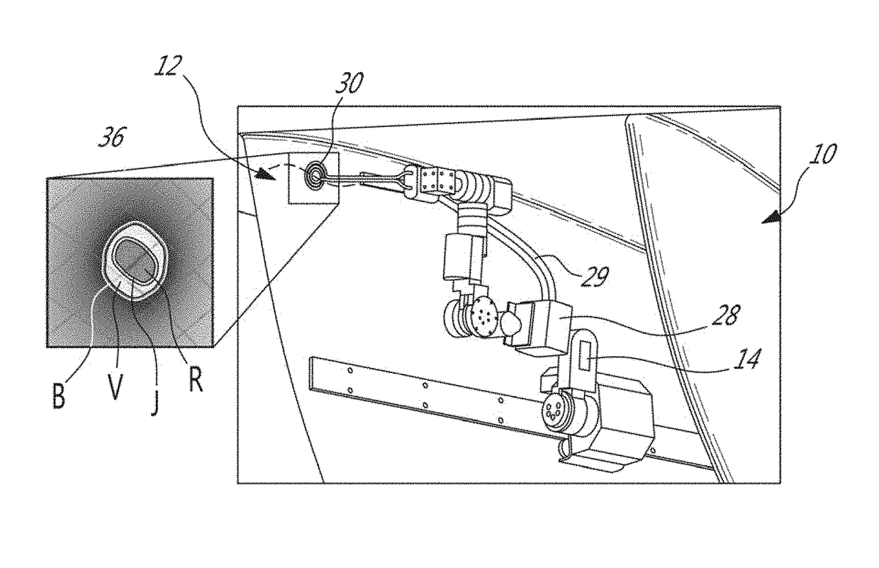
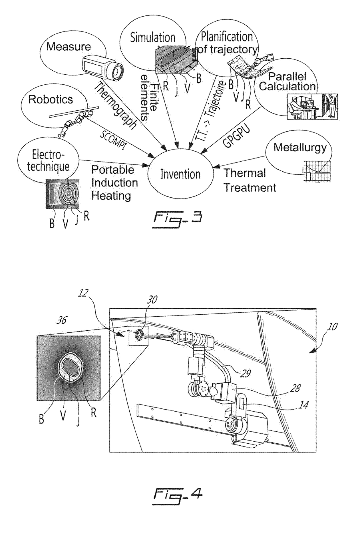
[0046]Referring to FIG. 4, a robotic system 10 is shown for the thermal treatment of a weld zone 12, according to a preferred embodiment of the invention. The system inc...


PUM

PropertyMeasurementUnit
Temperatureaaaaaaaaaa
Poweraaaaaaaaaa
Speedaaaaaaaaaa

Abstract

Method and system for thermal treatment by heat induction of a metal piece on a targeted zone. According to the method, the thermal treatment is carried out using a thermal element mounted on a robotic system for moving the thermal element along a cyclical trajectory on the targeted zone so as to heat the target zone and minimize the temperature deviations over the targeted zone.

Description

FIELD OF THE INVENTION[0001]The present invention relates to a system and method of repair by thermal treatment of a damaged metal piece.BACKGROUND OF THE INVENTION[0002]More than one third of the hydropower plants of Hydro-Québec consists of turbine wheels made of martensitic stainless steel 13Cr-4Ni (CA6NM). The wheels are aging and cracks resulting from fatigue loading appear in several facilities. For metallurgical reasons, repairs are so far carried out with austenitic 309L steel. The yield strength of this steel is half that of the base material. The resistance to cavitation is greatly reduced. The use of different steel to correct defects causes a microstructural heterogeneity in the heat affected zone (HAZ). The problem is even aggravated as the properties of the base material around the area where the crack has spread have not been able to withstand the passage of time. In summary, the weakening of the wheel due to the current repair process generates a recurring problem.[0...

Claims


Application Information

Patent Timeline
IPC IPC(8): B23P6/04H05B6/06H05B6/10B23K31/02C21D1/42C21D9/50C21D6/00C22C38/40B25J11/00H05B6/40
CPCB23P6/045B25J11/00H05B6/06H05B6/101H05B6/40C21D1/42B23K2203/05C21D6/004C22C38/40B23K31/02C21D2211/008B23K2201/001C21D9/50B23P6/007C21D2221/00B23K2101/001B23K2103/05Y02P10/25
Inventor BOUDREAULT, ERICHAZEL, BRUCELANTEIGNE, JACQUESCOTE, JEANLAGACE, MARINGENDRON, MATHIEU
Owner HYDRO QUEBEC CORP
Why Eureka
Try Eureka