Radio-frequency module

a radio frequency module and module technology, applied in the field of radio frequency modules, can solve the problems of not being able to suppress leakage through paths other than ground patterns, not being able to reduce or prevent the occurrence of the above-described coupling, and the isolation characteristics of each band are effectively improved

Active Publication Date: 2017-09-14
MURATA MFG CO LTD
View PDF2 Cites 18 Cited by
  • Summary
  • Abstract
  • Description
  • Claims
  • Application Information

AI Technical Summary

Benefits of technology

[0027]In other words, the receiver terminal connected to the second receive terminal is located farther from the first amplifier circuit. By disposing the terminals of the second separator circuit in this manner, it is possible to further reduce or prevent the occurrence of the abo

Problems solved by technology

More specifically, if the size of a radio-frequency module is reduced, harmonic components of a transmitting signal amplified in a low-band amplifier circuit are more likely to leak into a high-band receive circuit.
However, the radio-frequency module disclosed in Japanese Unexamined Patent Application Publication No. 2007-124202 is

Method used


Image

  • Radio-frequency module
  • Radio-frequency module
  • Radio-frequency module

Examples


Embodiment Construction

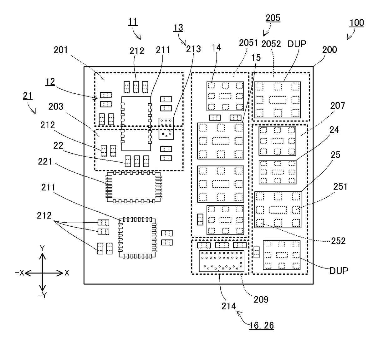
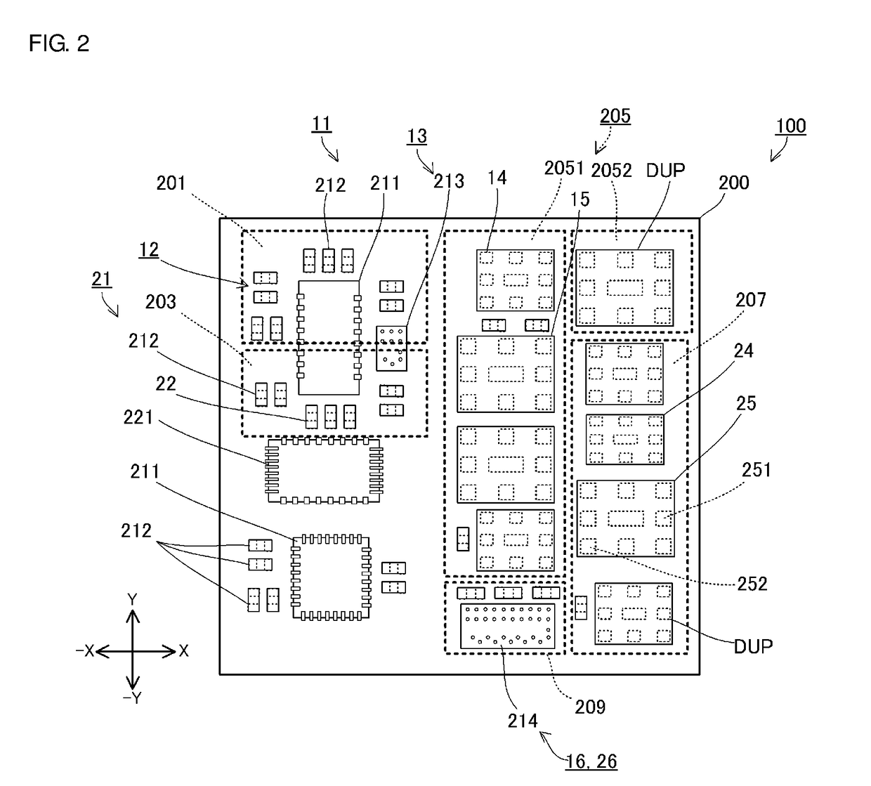
[0037]A radio-frequency module 100 according to a first preferred embodiment will be described below. The radio-frequency module 100 transmits and receives LTE (Long Term Evolution)-standard signals (for example, signals of about 700 MHz to about 2700 MHz). For transmitting and receiving signals, the radio-frequency module 100 amplifies a transmitting signal, separates a transmitting signal and a received signal from each other by frequency division, and switches between communication bands. The radio-frequency module 100 utilizes carrier aggregation, that is, the radio-frequency module 100 wirelessly transmits and receives signals of multiple bands at the same time.

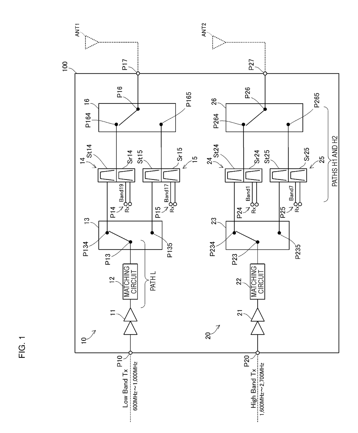
[0038]Details of the radio-frequency module 100 will now be described with reference to FIG. 1. FIG. 1 is a diagram illustrating a circuit example of the radio-frequency module 100.

[0039]As shown in FIG. 1, the radio-frequency module 100 includes a low-band transmitter-and-receiver 10 and a high-band transmitter-and-rece...


PUM


Abstract

A radio-frequency module includes a first transmitter-and-receiver that transmits and receives a signal in a first band, and a second transmitter-and-receiver that transmits and receives a signal in a second band higher than the first band. The first transmitter-and-receiver includes a first amplifier circuit and a first separator circuit and the second transmitter-and-receiver includes a second amplifier circuit and a second separator circuit. The first separator is located on a substrate between the first amplifier circuit and the second separator circuit, such that the first separator circuit is spatially interposed between the first amplifier circuit and the second separator circuit.

Description

CROSS REFERENCE TO RELATED APPLICATIONS[0001]This application claims the benefit of priority to Japanese Patent Application No. 2014-261518 filed on Dec. 25, 2014 and is a Continuation application of PCT Application No. PCT / JP2015 / 082824 filed on Nov. 24, 2015. The entire contents of each application are hereby incorporated herein by reference.BACKGROUND OF THE INVENTION[0002]1. Field of the Invention[0003]The present invention relates to a radio-frequency module which wirelessly transmits and receives signals of different bands at the same time.[0004]2. Description of the Related Art[0005]As an example of recent communication methods for wirelessly transmitting and receiving signals of different bands at the same time, carrier aggregation is known. In a radio-frequency module supporting carrier aggregation, an antenna, a receive circuit, an amplifier circuit for amplifying a transmitting signal, and a separator are required for each band.[0006]If the size of a radio-frequency modul...

Claims


Application Information

Patent Timeline
IPC IPC(8): H04B1/525H03J7/18H04B1/12G01S1/20H04B1/44H04B1/04
CPCH04B1/525H04B1/44H04B1/04H04B2001/045G01S1/20H03J7/186H04B1/123H03F1/02H03F3/24H04B1/0057
Inventor KOGURE, TAKESHIONO, ATSUSHINAGAMORI, HIROYUKI
Owner MURATA MFG CO LTD
Why Eureka
Try Eureka