Solar battery system

a solar energy and battery technology, applied in the direction of battery/fuel cell control arrangement, light to electrical conversion, electric devices, etc., can solve the problems of ecu temperature rise and ecu operation performance deterioration, and achieve the effect of suppressing temperature ris

Active Publication Date: 2017-09-21
TOYOTA JIDOSHA KK
View PDF7 Cites 18 Cited by
  • Summary
  • Abstract
  • Description
  • Claims
  • Application Information

AI Technical Summary

Benefits of technology

[0006]Incidentally, since the electric storage device outputs a relatively high voltage (for example, 200 V or more), presence or absence of abnormality such as overdischarge and overcharge, and other statuses are often monitored. It is, therefore, necessary to receive permission of charging the electric storage device from a monitoring device (such as an HV-ECU). Even while the electric storage device is being charged, the monitoring device needs to continue monitoring the electric storage device. Accordingly, when the electric storage device is charged during a period of time from ignition-off (IG-OFF) to ignition-on (IG-ON) of the vehicle (i.e., during parking of the vehicle), the monitoring device, which is essentially in a sleep state except for required minimum functions, needs to be shifted to a wake state. Consequently, in order to prevent increase in power consumption caused by maintaining the monitoring device in the wake state, a technique (so-called pumping charging) may be adopted in which the electric storage device is intermittently charged with the electric power generated from the solar battery during a period of time from the IG-OFF to the IG-ON of the vehicle.

Problems solved by technology

When the vehicle cabin is higher in temperature than the ECU, the pumping charging increases the amount of heat received from the outside, which may cause rise in temperature of the ECU and deterioration in operation performance of the ECU.

Method used


Image

  • Solar battery system
  • Solar battery system
  • Solar battery system

Examples


first embodiment

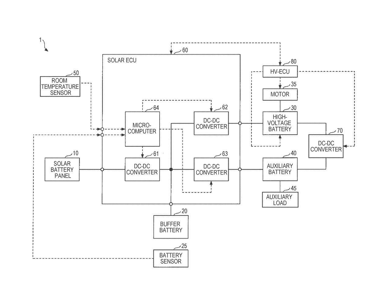
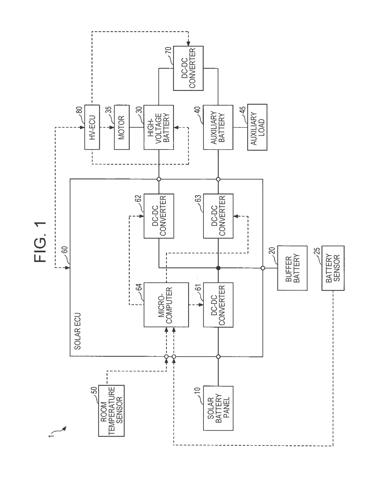
[0034]FIG. 1 is a block diagram schematically illustrating one example of the configuration of a solar battery system 1 according to the present embodiment. The solar battery system 1, which is mounted in a vehicle, includes a solar battery panel 10, a buffer battery 20, a battery sensor 25, a high-voltage battery 30, a motor 35, an auxiliary battery 40, an auxiliary load 45, a room temperature sensor 50, and a solar ECU 60. Hereinafter, unless otherwise specified, a term “vehicle” refers to a vehicle in which the solar battery system 1 is mounted.

[0035]The vehicle includes a DC-DC converter 70 and an HV-ECU (electronic control unit that performs integrated control of the entire vehicle in a motor vehicle) 80 as the elements relating to the solar battery system 1.

[0036]In FIG. 1, a solid line represents an electric power system, and a dotted line represents a control (signal) system.

[0037]The solar battery panel 10 is a panel-like module constituted of a plurality of solar battery c...

second embodiment

[0093]A description is now given of the second embodiment.

[0094]A solar battery system 1A according to the present embodiment is different from the first embodiment in the point that the solar ECU 60 is replaced with a solar ECU 60A and more specifically in the point that a temperature sensor 65A is added to be specific. The solar battery system 1A is different from the first embodiment in the point that the microcomputer 64 is replaced with a microcomputer 64A (see FIGS. 5 and 6) and more specifically in the point that the second charging control unit 643 is replaced with a second charging control unit 643A (see FIG. 6) and a temperature state determination unit 645A (see FIG. 6) is added. Hereinafter, the component members similar to those in the first embodiment are designated by similar reference signs, and a description is mainly given of the difference from the first embodiment.

[0095]FIG. 5 is a block diagram schematically illustrating one example of the configuration of the s...

third embodiment

[0108]A description is now given of the third embodiment.

[0109]A solar battery system 1B according to the present embodiment is different from the first embodiment in the point that the room temperature sensor 50 is replaced with a clock 50B (see FIG. 8). The solar battery system 1B is different from the first embodiment in the point that the solar ECU 60 is replaced with a solar ECU 60B (see FIG. 8), and more particularly in the point that the room temperature acquisition unit 644 is replaced with a room temperature acquisition unit 644B (see FIG. 9), and the microcomputer 64 is replaced with a microcomputer 64B (see FIGS. 8 and 9). Hereinafter, the component members similar to those in the first embodiment are designated by similar reference signs, and a description is mainly given of the difference from the first embodiment.

[0110]FIG. 8 is a block diagram schematically illustrating one example of the configuration of the solar battery system 1B according to the present embodiment...


PUM


Abstract

A solar battery system includes a first electronic control unit disposed in a vehicle cabin of a vehicle, the first electronic control unit including a control unit repeating a charging period and a stop period during a period of time from ignition-off to ignition-on of the vehicle, the charging period being a period of charging the electric storage device with generated electric power of a solar battery, the stop period being a period of stopping the charging of the electric storage device with the generated electric power of the solar battery. The control unit sets a length of each of the charging periods shorter as the temperature in the vehicle cabin is higher at the time of starting each of the charging periods.

Description

INCORPORATION BY REFERENCE[0001]The disclosure of Japanese Patent Application No. 2016-052704 filed on Mar. 16, 2016 including the specification, drawings and abstract is incorporated herein by reference in its entirety.BACKGROUND[0002]1. Technical Field[0003]The present disclosure relates to a solar battery system mounted in a vehicle.[0004]2. Description of Related Art[0005]There is known a solar battery system including solar batteries capable of supplying generated electric power to an electric storage device that supplies the electric power to a motor that drives a vehicle (see, for example, Japanese Patent Application Publication No. 2015-082866).SUMMARY[0006]Incidentally, since the electric storage device outputs a relatively high voltage (for example, 200 V or more), presence or absence of abnormality such as overdischarge and overcharge, and other statuses are often monitored. It is, therefore, necessary to receive permission of charging the electric storage device from a m...

Claims


Application Information

Patent Timeline
Patent Type & Authority Applications(United States)
IPC IPC(8): B60L11/18H02J7/35H02J7/00B60L8/00
CPCB60L11/1812B60L8/003H02J7/007H02J7/35B60L11/1851H02J7/0088B60L3/0084B60L2240/34B60L2240/36B60L2240/662Y02T90/16Y02T10/7072Y02T90/14B60L58/20H02J2310/48Y02T10/70Y02T10/72Y02T90/12B60L53/22
Inventor HARADA, TADAKAZU
Owner TOYOTA JIDOSHA KK
Why Eureka
Try Eureka