
Extruded metal flow 3D printer

a 3d printer and metal flow technology, applied in the field of 3d printers, can solve the problems of low precision and surface finish quality, high cost, and complex overall structure, and achieve the effects of simple structure, enhanced binding force, and enhanced print effect and model molding

Active Publication Date: 2017-09-28
ASIA AMERICA IND MFG INC
View PDF0 Cites 30 Cited by
  • Summary
  • Abstract
  • Description
  • Claims
  • Application Information

AI Technical Summary

Benefits of technology

The present invention has the following benefits: 1. Two lasers located under the printing head can preheat and melt metal layer printed from metal wire, improving print and molding effects. 2. The structure is simple and low manufacturing cost. 3. A water-cooling plant improves cooling effect, increasing service life and print effect. 4. An inert gas feeder prevents metal fluid oxidization and improves work quality to manufacture high quality metal r model products. 5. An open heating ring mounted at the lower end of tungsten steel nozzle heats only the lower end, preventing heating of metal wire through the ceramic tube bank too early and forming a continuous filar semisolid metal fluid to enhance print effect of printing head.

Problems solved by technology

At present, the 3D printer is universally used for forming plastic models, few 3D printers are used for forming metal models, and the metal models formed by the 3D printer for forming metal models have nonideal performance in precision and surface finish quality, and the overall structure is very complex, the cost is relatively high.

Method used


Image

  • Extruded metal flow 3D printer
  • Extruded metal flow 3D printer
  • Extruded metal flow 3D printer

Examples


Embodiment Construction

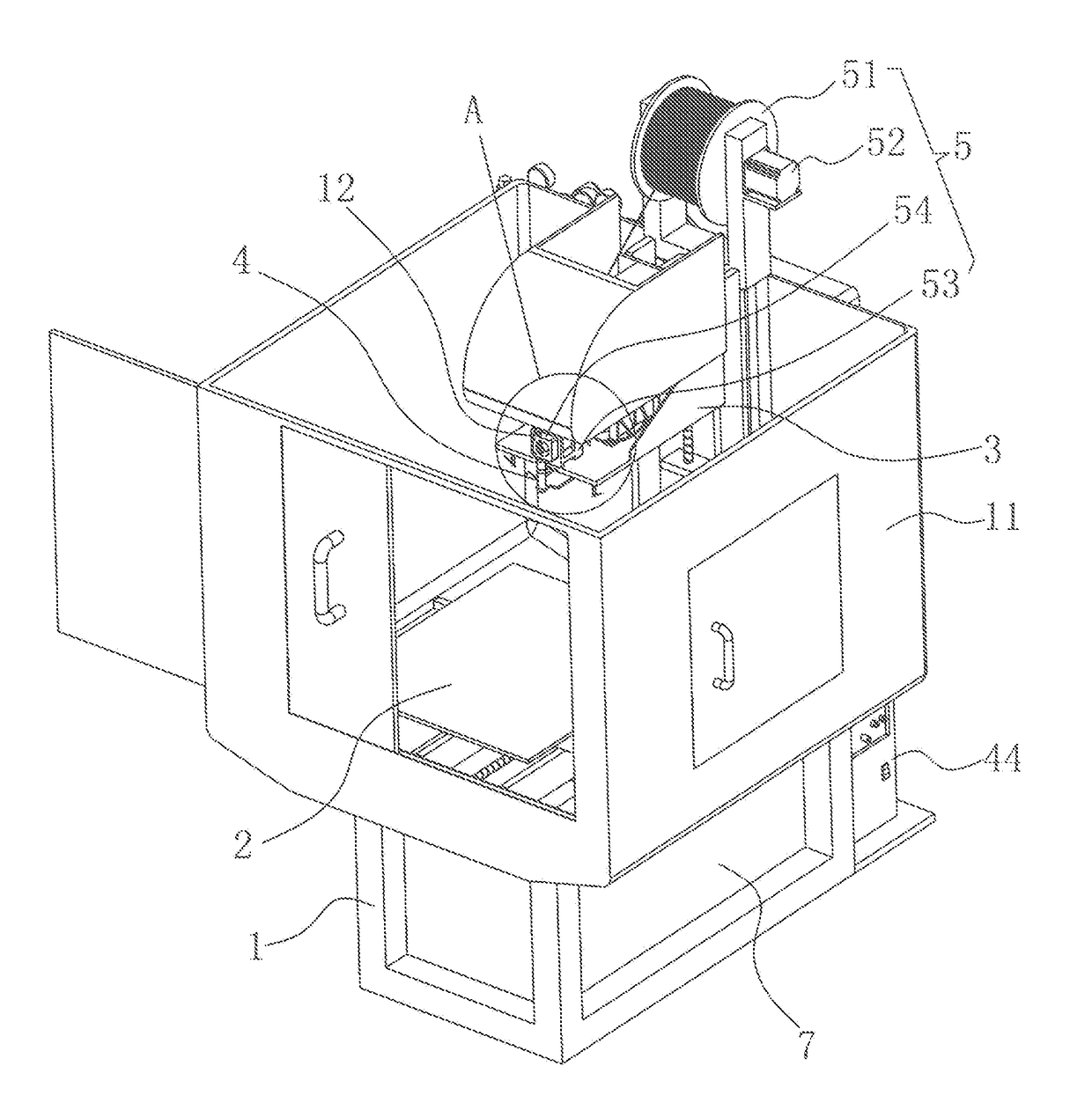
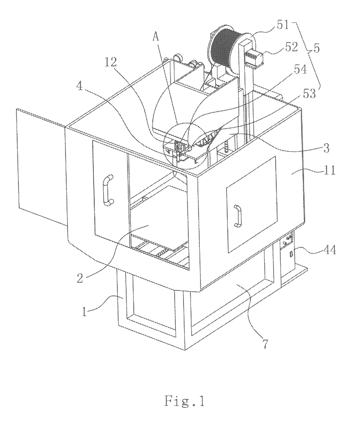
[0034]FIGS. 1-8 show an extruded metal flow 3D printer comprising: a frame (1) including a workbench (2) capable of moving along an X-axis and Y-axis direction, a head (3) capable of moving along an Z-axis direction, a printing device (4) installed in the head (3), a feeding device (5) mounted on the frame (1) and configured to convey a metal wire to the printing device (4), and a housing (11) installed on the frame (1).

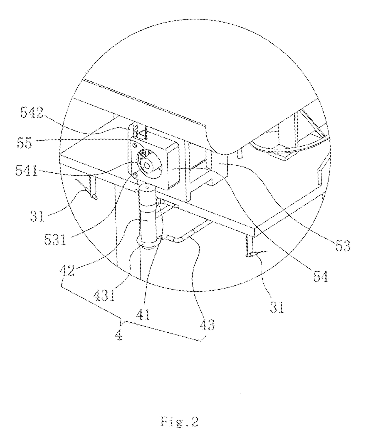
[0035]The printing device (4) includes a printing head (42) fixed in the head (3) via a connecting base (41), a high frequency coil (43) and a high frequency electric induction heating device (44) for heating the printing head (42); the printing head (42) including a tungsten steel nozzle (46), a ceramic tube bank. (47) disposed inside the tungsten steel nozzle (46), a high temperature resistant ceramic protective sleeve (48) sleeved on an external surface of the tungsten steel nozzle (46), and a stainless steel end cover (49) covered on an upper end of the tungsten ...


PUM

PropertyMeasurementUnit
temperatureaaaaaaaaaa
binding forceaaaaaaaaaa
diameteraaaaaaaaaa

Abstract

an extruded metal flow 3D printer comprising a rack including a workbench capable of moving along n X-axis and Y-axis direction, and a head capable of moving along an Z-axis direction; a printing device including a printing head, a highfrequency coil and a high frequency electric induction heating device; the printing heal including a tungsten steel nozzle, a ceramic tube bank, a high temperature resistant ceramic protective sleeve, and a stainless steel end cover; the tungsten steel nozzle having an extrusion hole; a feeding device; the head comprising at least one laser mounted on a lower end face thereof and configured to locally preheat and melt a metal layer printed from the metal wire or enhance a binding force between metal layers, so that the print effect and model molding effect of the present invention can be improved, enhancing the marketability.

Description

CROSS-REFERENCE TO RELATED APPLICATION[0001]This application claims priority to PCT Application No.: PCT / CN2014 / 090983, having a filing date of Nov. 13, 2014, based off of Chinese Application No 201410206527.X, having a filing date of May 15, 2014, the entire contents of which are hereby incorporated by reference.FIELD OF THE INVENTION[0002]The present invention relates generally to the technical field of 3D printer, and more particularly to a structurally simple and low cost extruded metal flow 3D printer for locally preheating and melting a metal layer printed using a metal wire or enhancing a binding force between metal layers, so as to improve the print effect and model molding effect greatly.BACKGROUND OF THE INVENTION[0003]The 3D printer is a machine of rapid forming technique. It is a technology to construct objects by printing layer by layer using binding material, such as powdered metal or plastic, based on digital model file. It was often used for modeling in die making an...

Claims


Application Information

Patent Timeline
Patent Type & Authority Applications(United States)
IPC IPC(8): B22F3/105
CPCB22F3/105B23K15/0086B22F2999/00B33Y30/00Y02P10/25B22F10/20B22F12/33B22F12/53B22F12/70B22F10/10B22F12/10B22F12/30B22F3/22B22F3/115B22F2202/11B22F10/00
Inventor FENG, JIAN
Owner ASIA AMERICA IND MFG INC
Learn More