
Filter housing

Active Publication Date: 2017-09-28
CAMFIL AB
View PDF0 Cites 3 Cited by
  • Summary
  • Abstract
  • Description
  • Claims
  • Application Information

AI Technical Summary

Benefits of technology

The present invention provides an air filter housing that makes replacing filters easier and safer. The housing has a resilient member that holds the filter in position during installation, reducing the risk of damage to the filter. This also allows for a more controlled clamping of the filter, improving the efficiency of the filter replacement process. The overall technical effects of the invention include increased convenience for filter replacement, reduced downtime and improved safety.

Problems solved by technology

Changing filters is typically done from the cleanroom side and involves substantial manual work in awkward positions.
Cleanrooms can also be very large, which means that the number of filters to be replaced can be substantial.
The awkward work of mounting filters in the filter housings also increases the risk of damage to the new filter as it is being mounted.

Method used


Image

  • Filter housing
  • Filter housing
  • Filter housing

Examples


Embodiment Construction

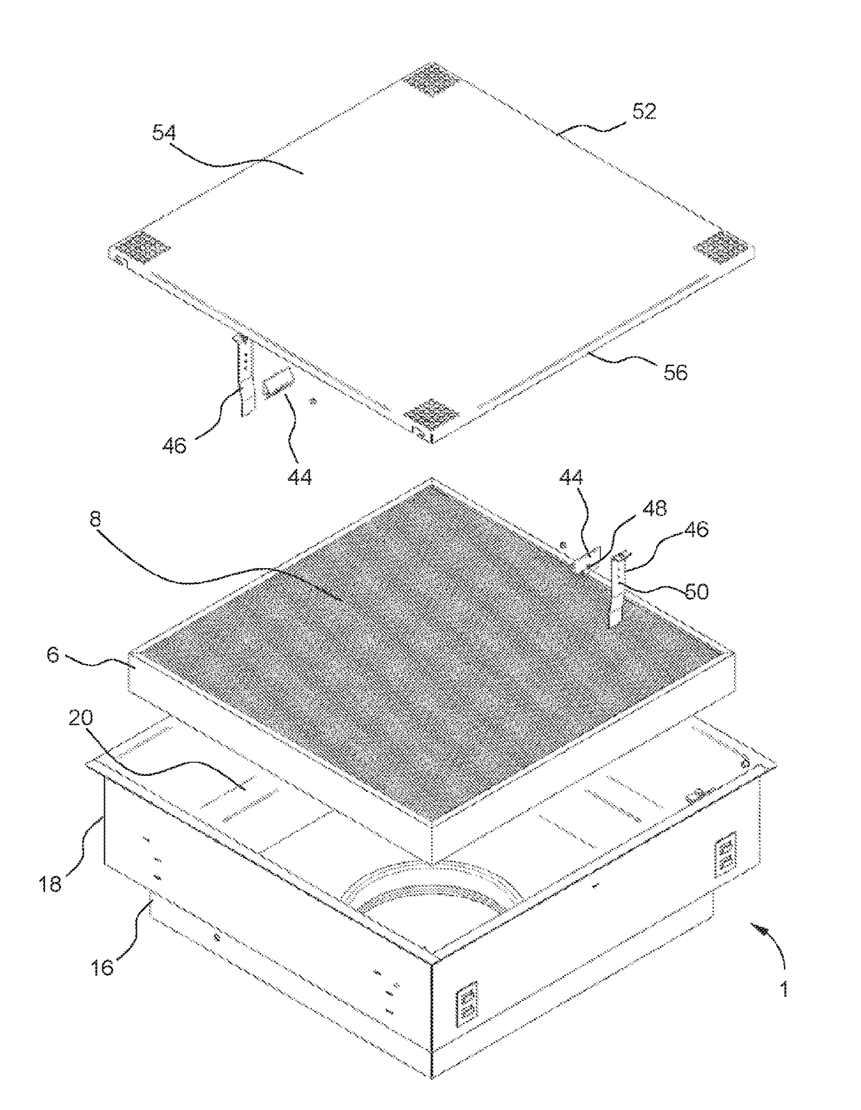
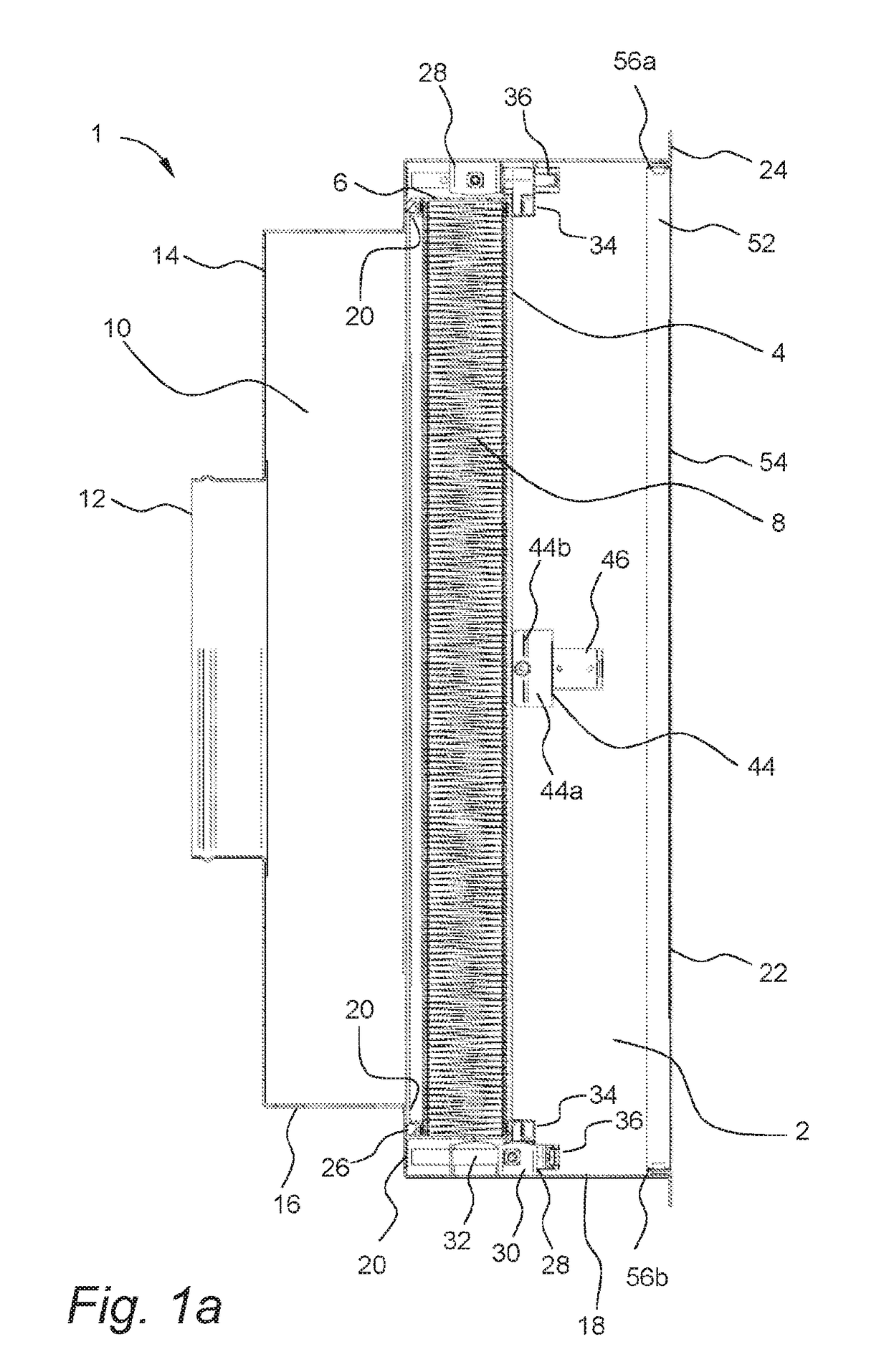
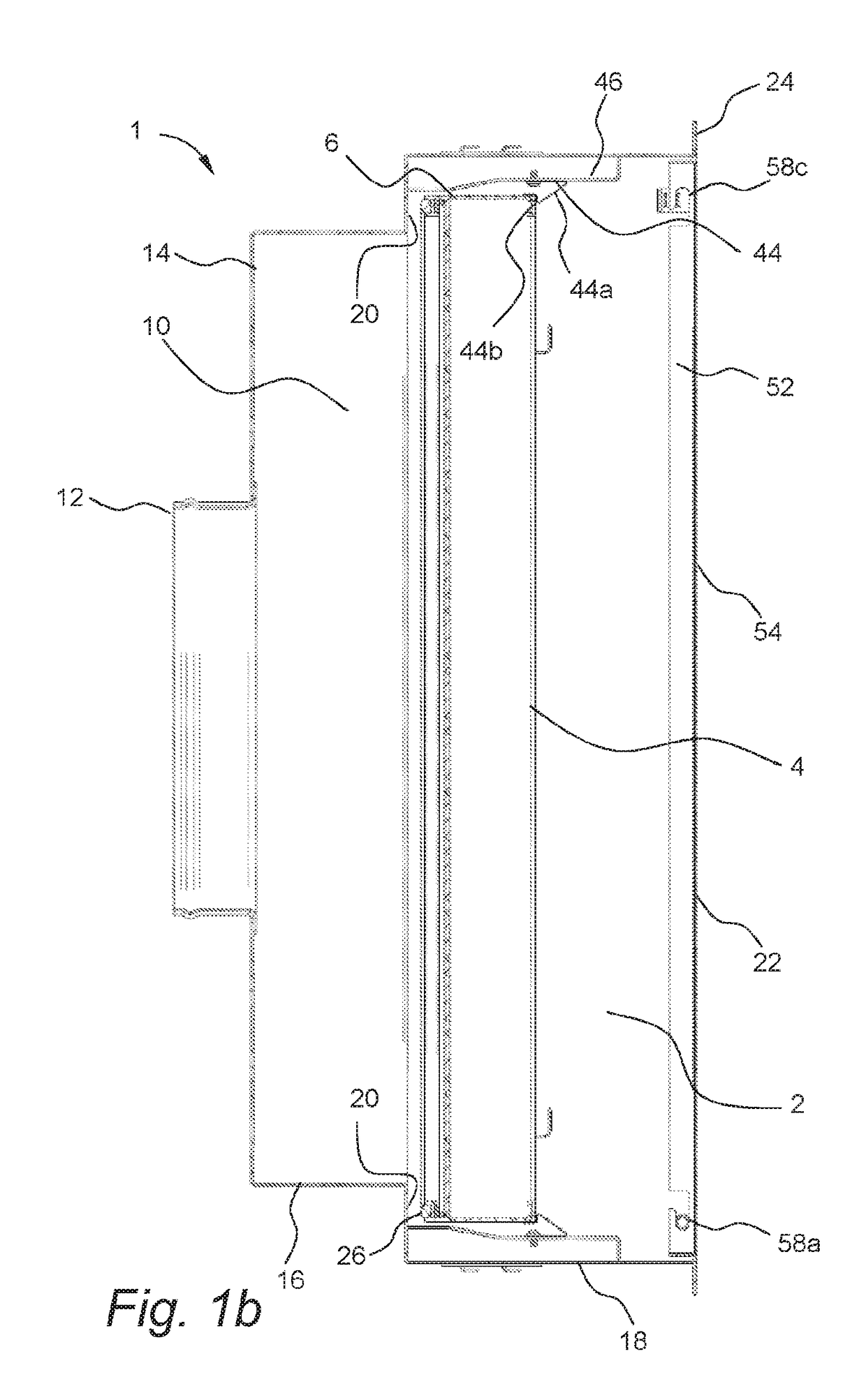
[0035]Referring to the drawings, an embodiment of a filter housing in accordance with the present disclosure is shown in FIGS. 1a, 1b and 2. The filter housing 1 forms part of an air circulating system for a cleanroom. A lower portion 2 of the filter housing is adapted to house a panel type filter 4, having a frame 6 and a filter medium 8 held within said frame, which filters air supplied to the cleanroom. Accordingly, the filter housing 1 encloses the sides of a panel type filter 4. An upper portion 10 of the filter housing 1 defines a plenum over the filter for delivering air under pressure to the top side of the filter. The bottom side of the filter 4 is exposed to the interior of the cleanroom. Air is directed into the plenum portion of the filter housing through an inlet 12 located on a top 14 or side wall 16 of the upper portion 10 of the filter housing 1. The inlet is connected via a duct to a fan or blower (not shown) which transports air into the plenum. The air flows downw...


PUM


Abstract

The present invention relates to an air filter housing for supplying air to a space, said air filter housing being configured to be arranged in a ceiling of said space, said housing having a mouth facing downward, said mouth comprising a sealing surface configured to receive a panel type air filter comprising a frame and a filter medium held within said frame, such that a sealing connection between said sealing surface and said frame is achieved, characterized in that said filter housing further comprises at least one resilient member arranged below the sealing surface such that when a panel type air filter is inserted into the mouth, the resilient member will be deformed by the filter frame as the filter passes the resilient member, and resume its original shape once the filter has passed, such that the filter is retained between the sealing surface and the resilient member. The present invention further relates to the use of a filter housing in a cleanroom, and to a method of mounting a panel type air filter in an air filter housing.

Description

TECHNICAL FIELD[0001]The present invention relates to filter housings for horizontally mounted panel type air filters, typically ceiling air filter housings, e.g. for use in cleanroom facilities or other spaces requiring air filtration.BACKGROUND OF THE INVENTION[0002]Cleanrooms are used, for example, in pharmaceutical and microelectronics manufacturing facilities and in hospitals to provide an atmosphere uncontaminated by dust, pollen, bacteria, molecular pollution, and the like.[0003]Cleanrooms typically comprise a sealed space to which filtered air is supplied by an air circulating system. In order to remove airborne contaminants the air is passed though one or more air filters before it enters the cleanroom. The air then leaves the room through outlet or exhaust filters mounted in a wall near the floor of the room, or in the floor itself.[0004]The inlet air filters are typically mounted filter housings in the ceiling of the cleanroom or in a false ceiling which is suspended from...

Claims


Application Information

Patent Timeline
IPC IPC(8): F24F13/28F24F13/08F24F3/16F24F3/167
CPCF24F13/28F24F13/08F24F2013/205F24F3/161F24F2221/14F24F3/16F24F13/085F24F3/167B01D46/001B01D46/0097B01D46/185B01D2279/51
Inventor HUGUES, MATHIEULJUNGSTROM, STEFAN
Owner CAMFIL AB
Learn More