
A resistor, a heat dissipater and a combinatory device of resistor and heat dissipater

Active Publication Date: 2017-09-28
NR ELECTRIC CO LTD +2
View PDF2 Cites 4 Cited by
  • Summary
  • Abstract
  • Description
  • Claims
  • Application Information

AI Technical Summary

Benefits of technology

The present invention provides a solution that allows for a more compact and space-saving combination of a resistor and heat dissipater. It also ensures that the electrical circuits are completely insulated from the cooling branch circuit to prevent any potential electrical malfunctions that might be caused by leakage of the inlet and outlet pipes of the heat dissipater. Additionally, the invention avoids the need for a terminal electrical lead-out wire that could be potentially dirty.

Problems solved by technology

Presently high-power resistors applied in domestic and abroad suffer very high power dissipation in operation of resistors, thus radiating methods to resistors must be designed.
The disadvantages thereof are vulnerably occurring chemical reactions, such like ionization and rustiness, in case resistors are under current for a long-time running, which affects the reliability of resistors and circulating cooling circuits enoiiiiously.
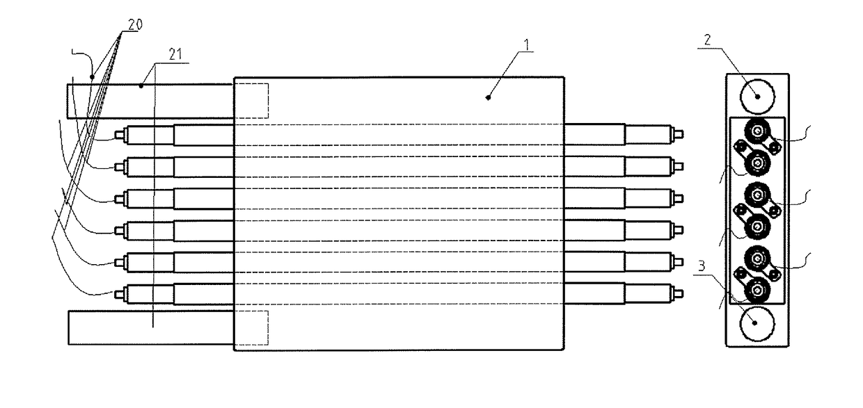
The disadvantages thereof are that, when the resistor is mounted in the heat dissipater, an electrical tail wire 20 on one side of the resistor and an inlet- and outlet-pipe 21 will affect each other mutually.
Meanwhile when for the inlet- and outlet-pipe 21 occurs weeping or other malfunctions, it may cause electrical damages, which reduces the reliability of the system enormously; moreover the one end of the resistor closing to the inlet- and outlet-pipe 21 of the heat dissipater can stretch out of the heat dissipater for a relatively long distance, which causes incompact structure and space waste of the combinatory device of the resistor and the heat dissipater; in occasions where resistors and heat dissipaters are applied frequently, the electrical tail wires closing to the one end of the inlet- and outlet-pipe of the heat dissipater make the wiring irregular.

Method used


Image

  • A resistor, a heat dissipater and a combinatory device of resistor and heat dissipater
  • A resistor, a heat dissipater and a combinatory device of resistor and heat dissipater
  • A resistor, a heat dissipater and a combinatory device of resistor and heat dissipater

Examples


Embodiment Construction

[0028]The technical solution of the present invention is further explained as below with reference to the accompanying drawings and detailed description.

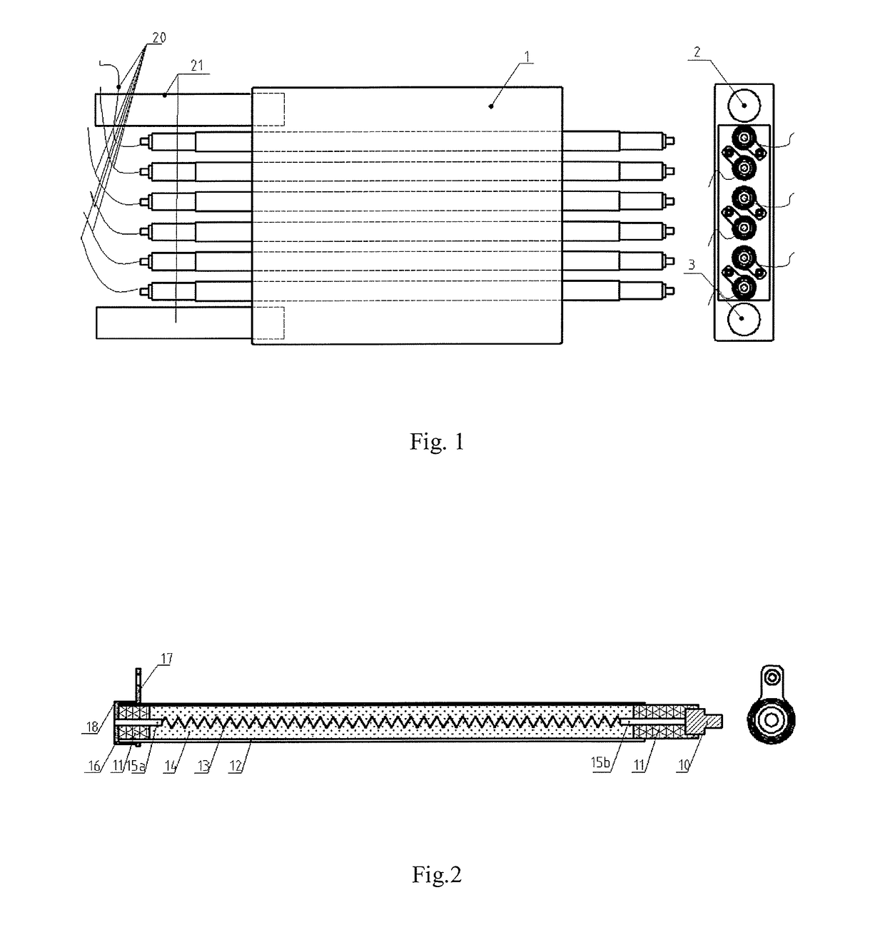
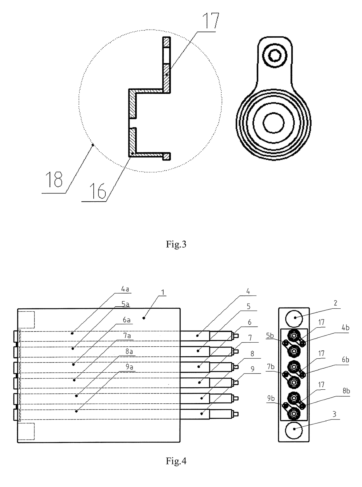
[0029]A structure scheme of an embodiment of a single resistor of the present invention is shown as in FIG. 2, wherein the resister comprises a metal end 10, an insulating part 11, a casing 12, a first metal bar 15a and a second metal bar 15b, a resistor wire 13, thermally conductive insulating fillers 14 and a metal connection mechanism 18. The casing 12 is normally made of metal materials, a cavity thereof where the resistor wire 13 is placed, and is filled with thermally conductive insulating fillers 14; both ends of the resistor wire 13 are connected respectively with one end of the first metal bar 15a stretching into the casing 12 and one end of the second metal bar 15b. The other end of the second metal bar 15b is connected with the metal end 10 as a head end of the resistor. A portion of the second metal bar 15b is exposing o...


PUM


Abstract

Disclosed are a resistor, a heat dissipater and a combinatory device of the resistor and the heat dissipater, and relates to the field of power electronics. The resistor is cylindrical, and comprises a metal end, an insulating part, a casing, metal bars, a resistor wire, thermally conductive insulating fillers and a metal connection mechanism. The metal connection mechanism of the resistor and the heat dissipater are connected by means of direct contact. The structure and the connection method can shorten the length of the resistor, completely insulate the electrical circuits of the resistor from the possible leakage of the water inlet- and outlet-pipe of the heat dissipater, and enable the combinatory device of the resistor and the heat dissipater to be structurally more compact and the connections thereof cleaner.

Description

TECHNICAL FIELD[0001]The present invention relates to a technical field of power electronics and power system, in particular relates to a resistor, a heat dissipater and a combinatory device of the resistor and the heat dissipater.BACKGROUND[0002]With the maturity of high-power power electronics technology and the demands on power system development, using high-voltage high-power resistors is necessary in more and more scenes.[0003]Presently high-power resistors applied in domestic and abroad suffer very high power dissipation in operation of resistors, thus radiating methods to resistors must be designed. Presently there are two kinds of common radiating methods. The first method is cooling resistor wires by immersing resistor wires in cooling fluid directly.[0004]The disadvantages thereof are vulnerably occurring chemical reactions, such like ionization and rustiness, in case resistors are under current for a long-time running, which affects the reliability of resistors and circul...

Claims


Application Information

Patent Timeline
IPC IPC(8): H01C1/08H01L23/46H01C1/01H01C1/12H01C1/028
CPCH01C1/08H01C1/12H01L23/46H01C1/01H01C1/028H01C1/14H05B3/48H01C1/014H01C3/10H01C1/082H01C3/00
Inventor FANG, TAIXUNZHANG, XIANGLIU, LEILI, ZHAOZHANG, GUANGTAIDING, FENGFENGZHANG, HUILIANG
Owner NR ELECTRIC CO LTD
Learn More