Optical shape sensing for instrument tracking in orthopedics

Pending Publication Date: 2017-10-05
KONINKLJIJKE PHILIPS NV
View PDF4 Cites 5 Cited by
  • Summary
  • Abstract
  • Description
  • Claims
  • Application Information

AI Technical Summary

Benefits of technology

[0011]Another optical shape sensing system includes an optical shape sensing module configured to receive feedback from one or more optical shape sensing fibers. One or more instruments have at least one optical shape sensing fiber connected thereto, the optical shape sensing fiber being employed to positionally track the instrument in an operating envir

Problems solved by technology

Any tracking attachments that are not visible by the cameras cannot provide a valid measurement.
It can be difficult to maintain an unobstructed path during all parts of the procedure, especially when, e.g., a bone is manipulated to test the dynamic biomechanics.
These CAS systems not only require line-of-sight, but are also only accurate within a defined volume.
This volume is with respect to the camera position and can be difficult to maintain throughout the procedure, especially during manipulation of the joint.
Such large attachments limit the physical wor

Method used


Image

  • Optical shape sensing for instrument tracking in orthopedics
  • Optical shape sensing for instrument tracking in orthopedics
  • Optical shape sensing for instrument tracking in orthopedics

Examples


Embodiment Construction

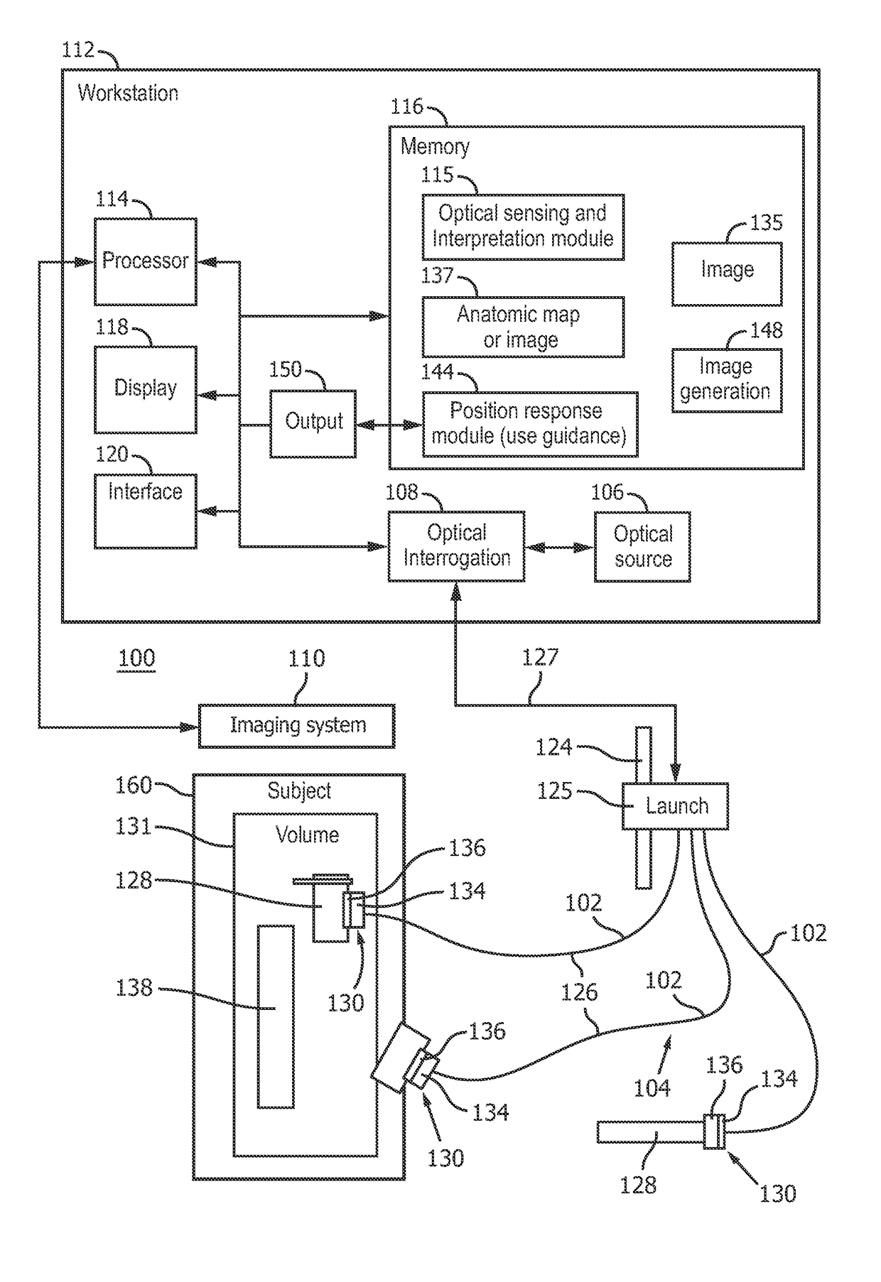
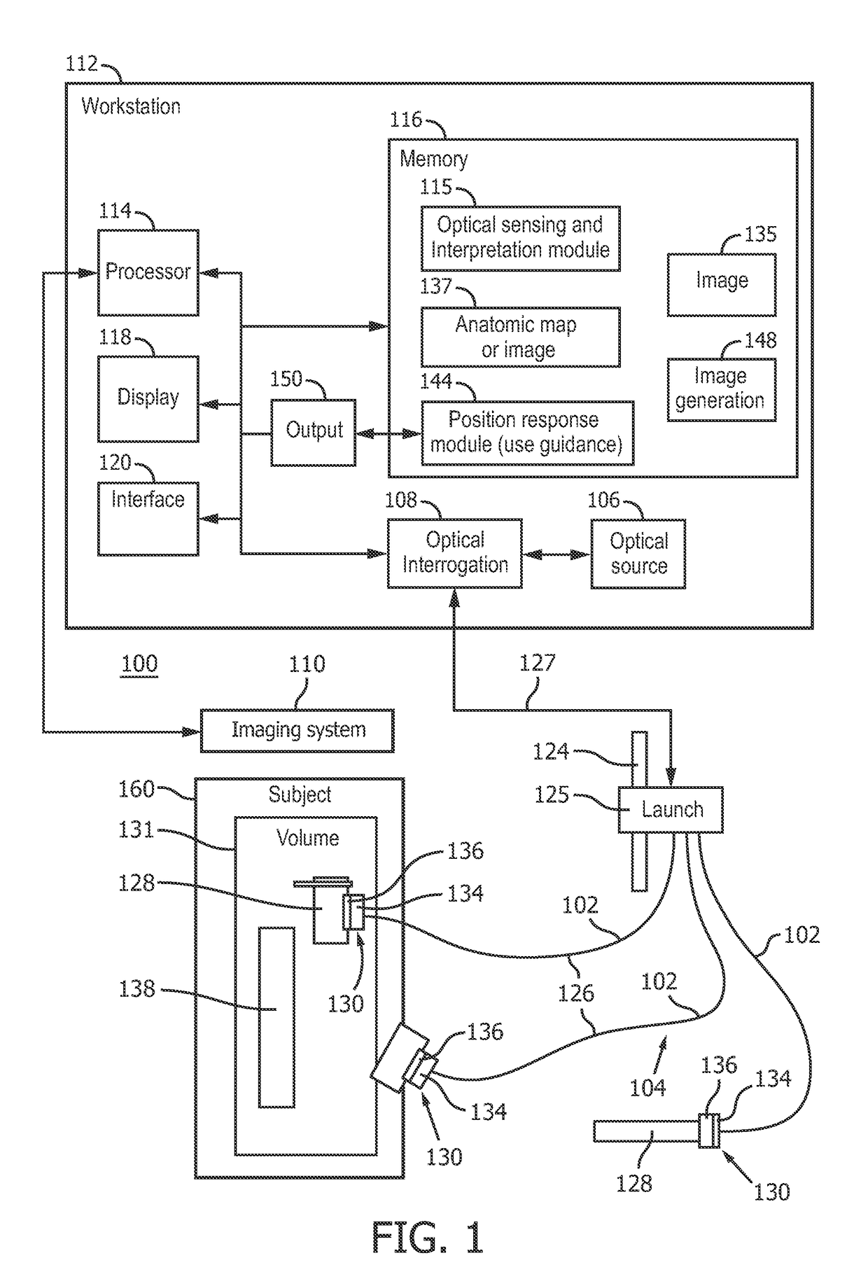
[0024]In accordance with the present principles, systems and methods are provided for optical shape sensing that can be used for displaying relative positions of instruments, fixtures, mechanical components, etc. on an anatomic map or other image during a surgical procedure. In one embodiment, the optical shape sensing fiber can be attached or mounted in or on a tool, instrument, fixtures, etc. The optical shape sensing measurement can be registered to the anatomical map. The position of the optical shape sensing markers with respect to an anatomic map can be displayed for a user. The optical shape sensing fiber may be attached to orthopedic or other instruments such as drills and cutting rigs to track their positions. In additional, optical shape sensing may be employed for tracking soft tissue and / or bones in orthopedic procedures. Optical shape sensing systems may be attached to the bones, ligaments, skin, inserts, etc. or combinations thereof.

[0025]In accordance with the present...


PUM


Abstract

An optical shape sensing system includes an attachment mechanism (130) being configured to secure an optical shape sensing fiber to an instrument, the optical shape sensing fiber being connected to the instrument and configured to identify a position and orientation of the instrument. An optical shape sensing module (115) is configured to receive feedback from the optical shape sensing fiber and register the position of the instrument relative to an operating environment. A position response module (144) is configured to provide feedback to an operator based on position or orientation of the instrument to guide usage of the instrument.

Description

BACKGROUND[0001]Technical Field[0002]This disclosure relates to medical instruments and more particularly to shape sensing optical fibers in medical applications for tracking medical instruments during computer aided procedures.[0003]Description of the Related Art[0004]Computer assisted surgery (CAS) systems are used for preoperative planning and intra-operative surgical navigation. In this context, preoperative planning refers to any computer assisted determination of surgical steps, such as cutting, incisions, targeting, etc. Planning can occur before or during a procedure. The preoperative planning often uses 2D or 3D images of a patient using any medical imaging modality (computed tomography (CT), magnetic resonance imaging (MRI), ultrasound, X-ray, endoscopy, etc.) or anatomical models (e.g., a knee model). In the context of CAS, surgical navigation refers to live tracking of instruments and patient anatomy enabling surgeons to precisely execute the preoperative plan. Surgical ...

Claims


Application Information

Patent Timeline
IPC IPC(8): A61B34/20A61B17/15A61B17/17G02B6/42
CPCA61B34/20G02B6/4292A61B2034/2061A61B17/1764A61B2034/2055A61B17/154
Inventor NOONAN, DAVID PAULFLEXMAN, MOLLY LARAPOPOVIC, ALEKSANDRA
Owner KONINKLJIJKE PHILIPS NV
Why Eureka
Try Eureka