Vehicular projection display apparatus

a technology of display apparatus and display face, which is applied in the direction of control devices, vehicle components, instruments, etc., can solve the problems of image distortion, adversely affecting visibility, and the image may be visually recognized by the driver, so as to improve the display characteristics of the technology, reduce the curvature of the image face, and improve the effect of display characteristics

Inactive Publication Date: 2017-10-05
YAZAKI CORP
View PDF3 Cites 15 Cited by
  • Summary
  • Abstract
  • Description
  • Claims
  • Application Information

AI Technical Summary

Benefits of technology

This patent describes a new technology for reducing the distortion of a virtual image in a vehicle's head-up display (HUD) system. By using a curved screen and improving the optical transfer efficiency, the technology corrects for the distortion caused by the vehicle's windshield and the HUD optical system. It also prevents the display from being affected by external light and allows for the use of small-angled light. Overall, this technology improves display quality without adding complexity to the HUD system.

Problems solved by technology

However, in an apparatus for projecting a display image by using the reflection of light on the face of the windshield as in the case of the HUD unit, distortion may occur in the image to be visually recognized by the driver.
In other words, distortion occurs in the image because the image is deformed by the reflection of light on the face of the windshield in an oblique direction and because the face itself of the windshield has a gradually curved shape.
Furthermore, since the curvature and the inclination angle of the windshield with respect to the horizontal plane (or the vertical plane) are different depending on the position on the windshield, various kinds of distortion may occur in the display image to be visually recognized in accordance with situations, thereby adversely affecting visibility.
Moreover, in the case that the HUD unit projects an image using a magnification optical system, aberration occurs due to the influence of the curved faces of the lenses and mirrors included in this optical system.
It has been known that aberration occurring due to the windshield and the HUD optical system of a vehicle is a factor of the distortion occurring in a display image (virtual image).
Furthermore, among various kinds of aberration, the aberration caused by the three-dimensional distortion of a display image (virtual image) due to “image face curvature” is assumed to be a factor of lowering display quality.
However, the image face curvature, i.e., three-dimensional distortion, cannot be corrected even if the aspherical mirror is used.
However, since the display face of the display device is generally flat, even if the image to be displayed on the display face has been distorted, only the planar distortion of the virtual image to be displayed can be corrected.
That is to say, since the distortion in the depth direction of the image (the direction of the optical axis at the time when the image is projected) cannot be corrected, the three-dimensional distortion of the display image (virtual image) due to the “image face curvature” cannot be corrected.
As a result, there is a problem that the utilization efficiency of the light is degraded and extra power consumption and heat generation occur in the light source.
Furthermore, in the case that external light, such as solar light, enters the face of the screen, since this external light scatters, there is a problem that the visibility of display light is degraded.
Hence, in the case that a display device having a small viewing angle and having luminance characteristics varying significantly depending on the viewing angle, such as a TN liquid crystal (twisted nematic liquid crystal) display device, is used, it is difficult to obtain excellent luminance characteristics in the virtual image display of the HUD unit.
However, it is inevitable that the structure of the image display apparatus becomes complicated.

Method used


Image

  • Vehicular projection display apparatus
  • Vehicular projection display apparatus
  • Vehicular projection display apparatus

Examples


Embodiment Construction

[0049]Specific embodiments according to the present invention will be described below referring to the respective accompanying drawings.

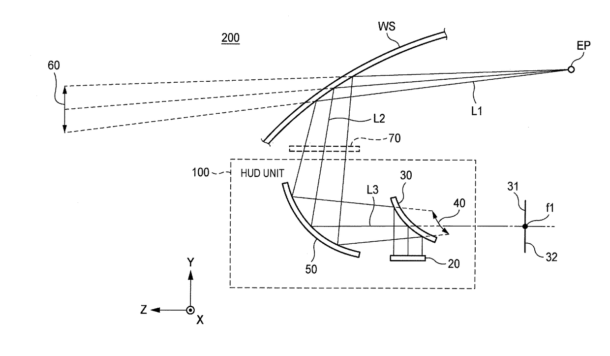
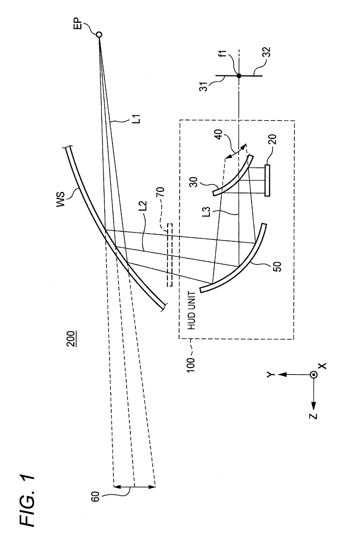
[0050]First, a configuration example of a vehicular projection display apparatus will be described. FIG. 1 shows the positional relationship of respective components of the vehicular projection display apparatus in the case that a vehicle equipped with the vehicular projection display apparatus, i.e., an HUD unit 100, is viewed from its side.

[0051]The HUD unit 100 shown in FIG. 1 is accommodated inside the dashboard of the vehicle and is configured so as to be able to emit light including a display image upward from an opening section 70 formed in part of the upper face of the dashboard.

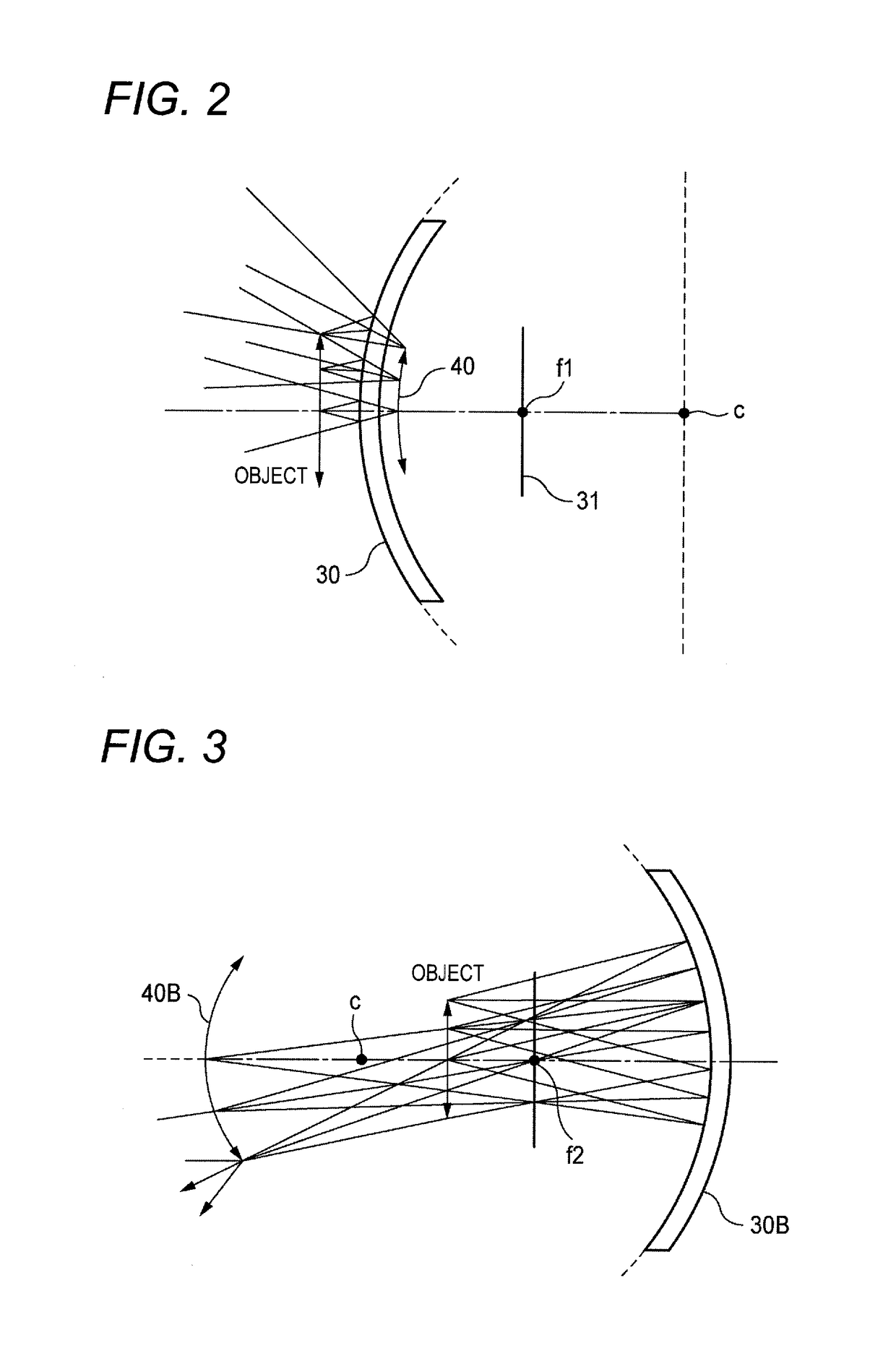
[0052]A display device 20, a convex mirror 30, a concave mirror 50 and a display control section, not shown, are provided inside the HUD unit 100. The display device 20 may be a display device, such as a transmission liquid crystal display panel, or a projector incor...


PUM


Abstract

A vehicular projection display apparatus includes: an intermediate image forming optical member; a display device disposed to project light including a display image to the intermediate image forming optical member, and to form an intermediate image as a virtual image or a real image, and an HUD optical system which receives the light of the intermediate image formed by the intermediate image forming optical member, which guides the light to a reflecting face of a windshield of a vehicle or a light reflecting member in a vicinity of the windshield, and which projects the light to allow the display image to be visually recognized as a virtual image at a predetermined eye point. The intermediate image forming optical member forms the intermediate image in a state in which at least part of the intermediate image is curved from a flat plane with respect to the display device.

Description

CROSS-REFERENCE TO RELATED APPLICATION(S)[0001]This application is based on and claims priority from Japanese Patent Application (Application No. 2016-065763) filed on Mar. 29, 2016, the entire contents of which are incorporated herein by reference.BACKGROUND1. Field of the Invention[0002]The present invention relates to a vehicular projection display apparatus for performing display by using, for example, the light reflection of the windshield (window glass) provided ahead of the driver in a vehicle.2. Description of Related Art[0003]In the case that information required by the driver in a vehicle, such as vehicle speed and guide display on a navigation system, is displayed, a head-up display (HUD) apparatus has been used in some cases to improve the visibility of the display at the time when the driver looks at the display during driving.[0004]In a head-up display apparatus for general vehicles, an optical path is formed so that the image of light including various kinds of inform...

Claims


Application Information

Patent Timeline
IPC IPC(8): G02B27/01B60K35/00G09G3/00
CPCG02B27/0101G09G3/002B60K35/00B60K2350/2017B60K2350/2052B60K2350/1056G09G2380/10G02B2027/011G02B17/0642B60K35/211B60K2360/334
Inventor NARUSHIMA, NORIAKIWATANABE, TAKEYOSHI
Owner YAZAKI CORP
Why Eureka
Try Eureka