Method of designing and manufacturing a distributor bar for applying a viscous foamable liquid mixture onto a laminator

a technology of foamable liquid and distributor bars, which is applied in the direction of process and machine control, chemical/physical processes, program control, etc., can solve the problems of multi-dimensional problems that cannot be easily solved without undue burden, and the application gives no guidance about potential problems, etc., to achieve high speed, high reactivity, and the effect of reducing the burden

Active Publication Date: 2017-10-05
HUNTSMAN INT LLC
View PDF3 Cites 12 Cited by
  • Summary
  • Abstract
  • Description
  • Claims
  • Application Information

AI Technical Summary

Benefits of technology

[0186]Preferably the inner diameter decreases linearly from a value Ddev at the center to a value α.Ddev at the outer ends because that is easy to simulate and to produce, but this is not absolutely required for achieving the advantageous effects of the present invention, and other smooth transition functions may also be used, for example, the cross-sectional area of the inner space 5 may be varied linearly from π.Ddev2 / 4 at the center to α.π.Ddev2 / 4 at the outer ends.
[0187]Distributor bars according to the first embodiment can then be represented by the following set of parameters (see FIG. 21 and FIG. 22):
[0188]Nholes denoting the total number of holes (exit pipes) in the distributor bar, (as discussed above, “Nholes” is considered a “variable” or a “given”, depending on the problem space),
[0189]Ndev denoting the number of devices (or “cooperating sub-bars”) together forming “the” distributor bar,
[0190]Ddev denoting the internal diameter of the main chamber 5, at the inlet of the device (i.e. the tapered inner volume 5, excluding the exit pipes),
[0191]α.Ddev denoting the internal diameter of the main chamber of the device (i.e. the tapered inner volume, excluding the exit pipes), at its outer ends,

Problems solved by technology

Apart from listing very broad parameter ranges, this application gives no guidance about potential problems of laminators, and / or how good laminators are to be designed.
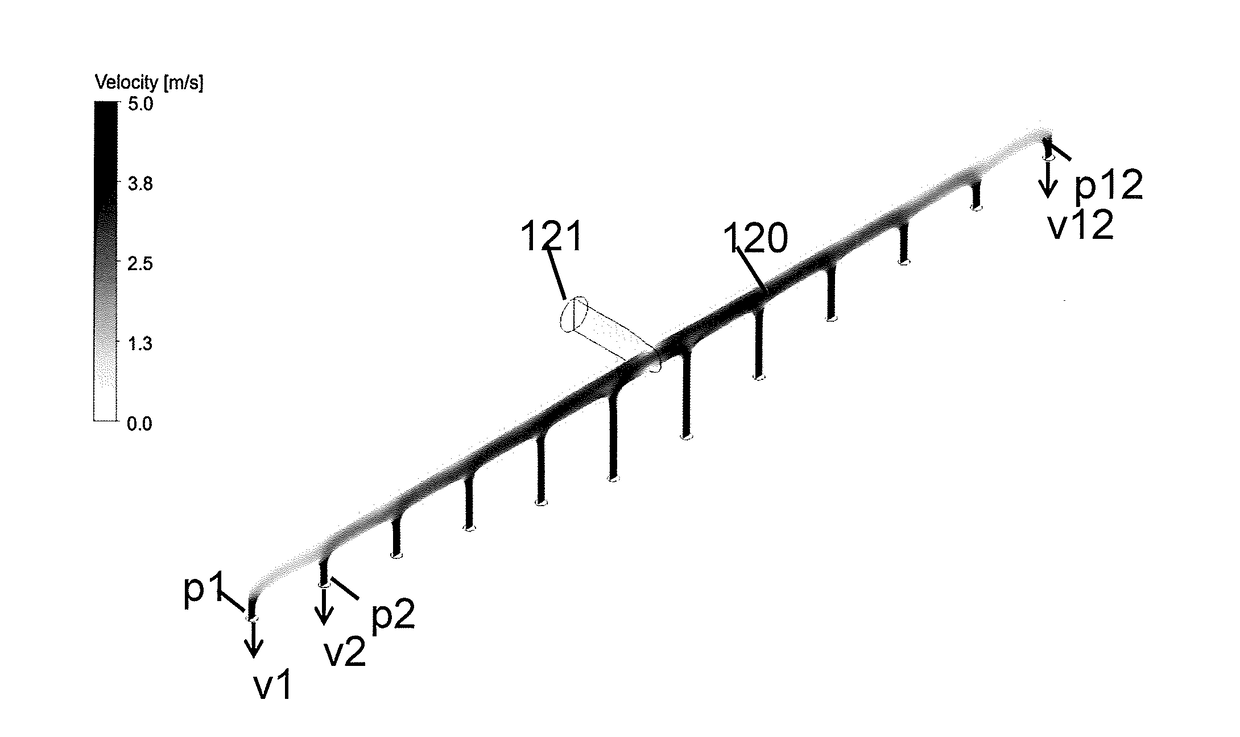
The publication provides some parameters which may be optimized with the intention to keep the velocity of the reaction mixture in the tube or on exiting the holes constant, however, the application does not offer a concrete solution of how exactly that intention can be achieved.
Given the large number of variables which need to be defined, the suggested solution is actually a multi-dimensional problem which cannot be easily solved without undue burden.
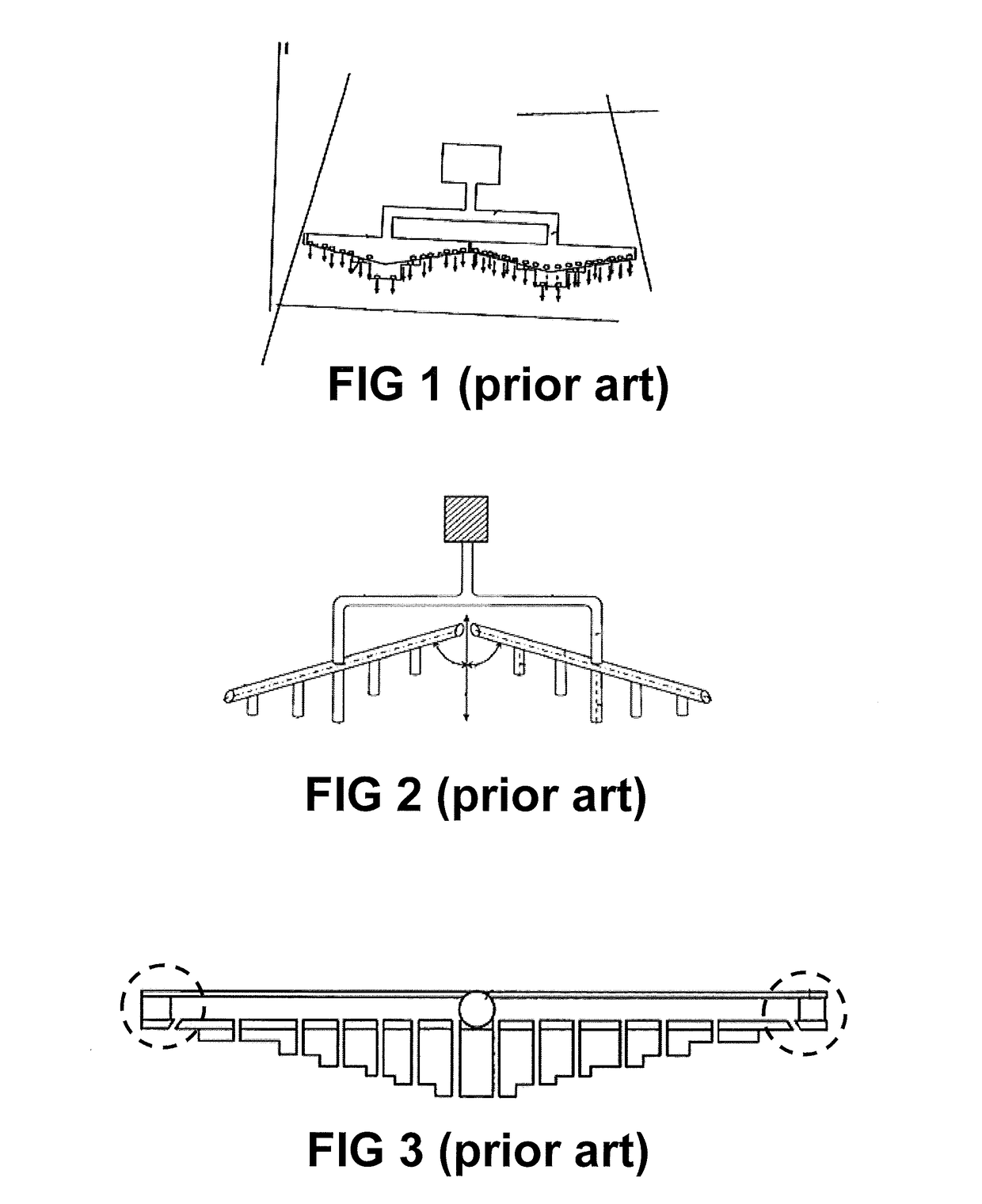
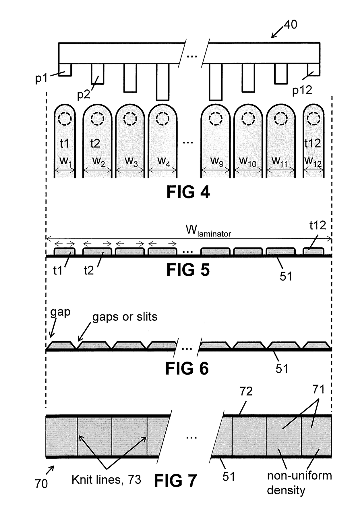
All prior art systems have as a goal to lay down a mixture layer that is as uniform as possible over the entire width of the top layer (e.g. sheet or laminator), but all seem to fail to describe in sufficient detail how this goal is to be achieved.
While this goal may be relatively easy to achieve for relatively low laminator speeds (e.g. less than 10 m / min) in combination with a foamable mixture with a relatively low reactivity (e.g. having a cream time higher than 10 s), this goal is not automatically achieved, and actually becomes a real technical challenge at relatively high laminator speeds (e.g. above 20 m / min or above 30 m / min or even higher), or stated differently at a flow rate of the foamable liquid mixture of at least 0.100 L / s per meter length of the distributor bar, especially when viscous foamable mixtures are used with a higher reactivity (which is usually the case for production lines with higher laminator speeds).

Method used


Image

  • Method of designing and manufacturing a distributor bar for applying a viscous foamable liquid mixture onto a laminator
  • Method of designing and manufacturing a distributor bar for applying a viscous foamable liquid mixture onto a laminator
  • Method of designing and manufacturing a distributor bar for applying a viscous foamable liquid mixture onto a laminator

Examples


first embodiment

[0182]FIG. 21 to FIG. 26 illustrate several examples of a first embodiment of a distributor bar according to the present invention, dedicated for particular production-lines.

[0183]The geometry of the distributor bar 210, 230, 240, 250, 260 of the first embodiment is chosen to have an inner space 5 (or “main channel”) with a substantially straight center line 6 (in its longitudinal direction). The inner space 5 of the distributor bar is tapering towards its outer ends (excluding the exit pipes, which have a constant inner diameter Dhole), whereby the inner diameter decreases (e.g. linearly) from a first value Ddev near the inlet to a second value α.Ddev at the outer ends (left and right in FIG. 22), where a is a constant value chosen in the range from 0.50 to 0.95, preferably in the range from 0.60 to 0.95, more preferably in the range of 0.75 to 0.80. The main reason for reduction of Ddev to αDdev is to reduce residence time and maintain a minimum speed to mitigate against fouling. ...

example 1

[0230]The following parameters of the production line are given:

[0231]Qtotal=3.6×10⁻⁴ m3 / s

[0232]Wpanel=1.0 m

[0233]n(fluid)=0.9

[0234]Vline=15 m / min

[0235]Using steps (a) to (h) of the design method described above, the following set of parameters of a distributor bar 230 according to an embodiment of the present invention, shown in FIG. 23, were chosen or calculated:

[0236]Ndev=2

[0237]Nholes=12×2=24

[0238]Ddev=8.0×10⁻³ m

[0239]Dhole=2.4×10⁻³ m

[0240]α=0.8

[0241]tdev=0.11 s

[0242]Vexit=3.3 m / s

[0243]W=0.21 m

[0244]K=3.7×10⁻² m

[0245]These values can then be used for starting the simulations and iterations, and for calculating the lengths of the exit pipes.

[0246]It is pointed out that there is no unique solution for this production-line, and other solutions for this same production-line may also be possible, as explained above, and as can be appreciated by the steps of the proposed design method. For example if Ddev is chosen slightly smaller, say e.g. equal to about 7.0×10⁻³ m, then a completel...

example 2

[0249]In a second example, the following parameters of the production line are given:

[0250]Qtotal=4.7×10⁻⁴ m3 / s, Wpanel=1.2 m, Vline=20 m / min, n(fluid)=0.9.

[0251]And a possible solution obtainable via the design method described above would be:

[0252]Ndev=2, Nholes=16×2=32, Ddev=8.5×10 3 m, Dhole=2.3×10⁻³ m,

[0253]α=0.8, tdev=0.12 s, Vexit=3.5 m / s, W=0.26 m, K=41×10−3 m.

[0254]Again, these values can then be used for starting the simulations, and for calculating the lengths of the exit pipes. This distribution bar 240 is illustrated in FIG. 24.


PUM

PropertyMeasurementUnit
exit velocitiesaaaaaaaaaa
residence timeaaaaaaaaaa
speedaaaaaaaaaa

Abstract

Method of designing and manufacturing a distributor bar for use in a production line comprising a mixing head for providing a viscous foamable liquid mixture, a laminator with a predefined speed of at least 20 m / min, the distributor bar having a central inlet fluidly connected to a number of outlets via a main channel. The method comprises: choosing (3001) a geometry for the distributor bar and defining a set of geometrical parameters; assigning (3002) values to said parameters; creating (3003) a virtual model; simulating (3005) flow in said model by performing a Computational Fluid Dynamics simulation (CFD), taking into account (3004) a non-Newtonian shear thinning model; e) evaluating the simulated flow; building (2007) a physical distributor bar. A distributor bar, a production line, and a computer program product.

Description

FIELD OF THE INVENTION[0001]The present invention relates to devices for applying a foamable reaction mixture onto a layer, such as onto a metal sheet or a laminator for making foam insulation panels. More in particular, the present invention relates to a method of designing and manufacturing a distributor bar for applying a viscous foamable liquid mixture onto such layer, to a distributor bar so designed and manufactured, and to a production line comprising such a distributor bar, and a computer program product for performing at least some steps of said method.BACKGROUND OF THE INVENTION[0002]Systems for applying a viscous foamable mixture, e.g. a mixture for generating polyurethane (PU) foams or polyisocyanurate (PIR) foams, are widely practiced nowadays. Such systems typically have a first (lower) continuously operating belt system, also referred to herein as “laminator”, upon which the viscous foamable mixture is laid down, and a second (upper) continuous belt system for forming...

Claims


Application Information

Patent Timeline
Patent Type & Authority Applications(United States)
IPC IPC(8): G05B19/4099B22C1/22B33Y10/00B29C67/00B01F3/04B33Y80/00B33Y50/02B05C5/02B29C44/34B29C44/32B29C44/46B29C45/00
CPCG05B19/4099G05B2219/49007B22C1/2273B33Y10/00B29C67/0055B29C45/0001B33Y80/00B33Y50/02B29C67/0062B05C5/0245B05C5/027B05C5/0291B29C67/0088B29C44/468B29C44/3442B29C44/32B01F3/04446B29L2023/22B29K2055/02B29K2077/00B29K2075/00B01F2215/0036G05B2219/49004G05B2219/35134B29C44/461B05B1/20B29C64/106B29C64/124B29C64/386Y02P80/40B01F23/235B01F2101/2204
Inventor BRENNAN, MARK JOSEPH
Owner HUNTSMAN INT LLC
Why Eureka
Try Eureka