Thermoelectrochemical Heat Converter

a heat converter and electrochemical technology, applied in the direction of indirect fuel cells, temperature-sensitive devices, cell components, etc., can solve the problems of reducing and affecting the performance of new direct energy conversion approaches

Inactive Publication Date: 2017-10-05
THE BOARD OF TRUSTEES OF THE LELAND STANFORD JUNIOR UNIV
View PDF1 Cites 5 Cited by
  • Summary
  • Abstract
  • Description
  • Claims
  • Application Information

AI Technical Summary

Benefits of technology

[0006]The device is the first to directly convert the entropy of a hot gas to electrical work without the need of overpressures. The device can be operated as an open system with net flow of gas, or as a closed-loop system with recirculation. In the open-system case, an external pump is not necessary to maintain operational pressures. The device offers potential improvements in heat conversion efficiency, temperature range, and power per unit weight over a thermoelectric.
[0008]In some embodiments, membranes can be connected in series or in parallel to increase voltage or current output, respectively. A pump can be attached to recirculate gas in the system. The device can be connected with others, such as thermoelectric generators, for more efficient use of waste heat.

Problems solved by technology

Almost 90% of the world's primary energy consumption occurs through the use of heat, and approximately 60% of this thermal energy is lost as rejected waste heat.
However, it has been difficult to optimize the performance of new direct energy conversion approaches because of the inability to decouple entropy change from thermal and electrical transport in materials and continuously operating devices.
Electrochemical sodium heat engines, which have demonstrated high efficiency and reasonable scalability, have stringent temperature requirements and stability issues.
Thus, it remains an unsolved challenge in direct heat-to-electricity conversion to realize continuous thermodynamic cycles that completely decouple entropy, heat and charge transport and operate across a broad range of temperatures.

Method used


Image

  • Thermoelectrochemical Heat Converter
  • Thermoelectrochemical Heat Converter
  • Thermoelectrochemical Heat Converter

Examples


Embodiment Construction

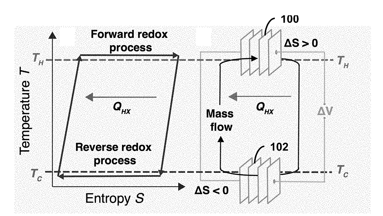
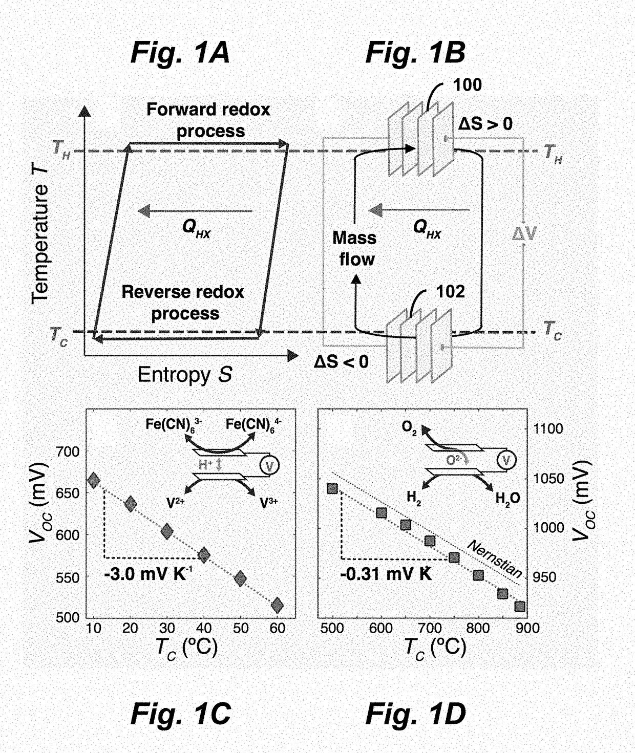
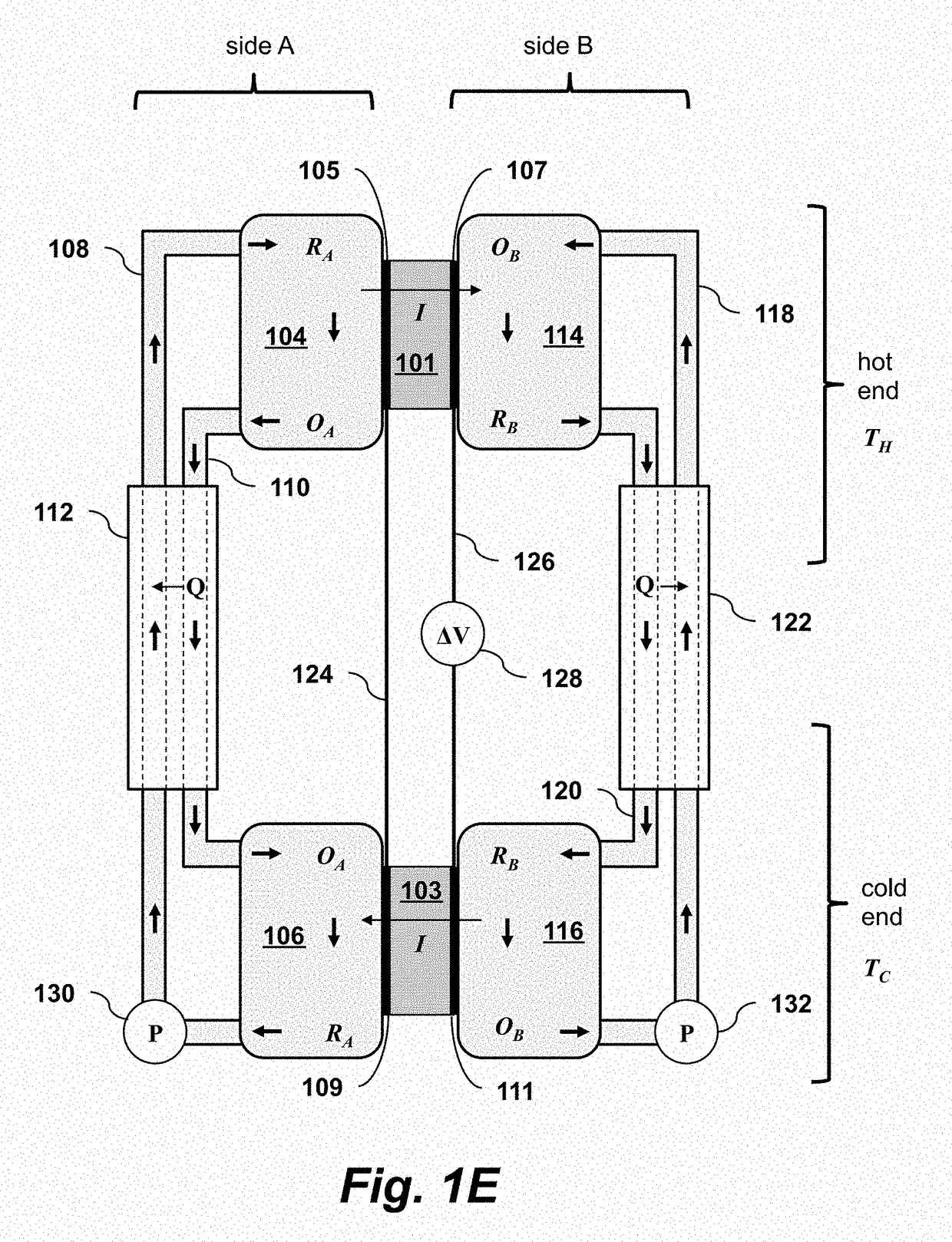
[0021]Embodiments of the present invention provide continuous electrochemical heat engines based on two redox-active working fluids separated by ion-selective membranes. As shown in FIGS. 1A-B, a first electrochemical cell 100 runs a forward redox reaction at a hot temperature TH, gaining entropy, and a second cell 102 simultaneously runs the reverse process at a cold temperature TC, expelling entropy. Counterflow heat exchange between the reduced and oxidized fluid streams decreases irreversible heat loss between hot and cold temperature reservoirs. This technique allows for the independent optimization of entropic, electrical, and thermal processes: whereas the redox reactions determine α, the ion-selective membranes determine ρ, and a heat exchanger between the two fluids sets an effective κ. The stability and kinetics of the redox fluid and the electrochemical cell set the cycle temperature, which can range from well below room temperature to 1000° C. Unlike in TE or TG systems,...


PUM

PropertyMeasurementUnit
temperatureaaaaaaaaaa
voltageaaaaaaaaaa

Abstract

A direct thermoelectrochemical heat-to-electricity converter includes two electrochemical cells at hot and cold temperatures, each having a gas-impermeable, electron-blocking membrane capable of transporting an ion I, and a pair of electrodes on opposite sides of the membrane. Two closed-circuit chambers A and B each includes a working fluid, a pump, and a counter-flow heat exchanger. The chambers are connected to opposite sides of the electrochemical cells and carry their respective working fluids between the two cells. The working fluids are each capable of undergoing a reversible redox half-reaction of the general form R→O+I+e−, where R is a reduced form of an active species in a working fluid and O is the oxidized forms of the active species. One of the first pair of electrodes is electrically connected to one the second pair of electrodes via an electrical load to produce electricity. The device thereby operates such that the first electrochemical cell runs a forward redox reaction, gaining entropy, and the second electrochemical cell runs a reverse redox reaction, expelling entropy.

Description

CROSS-REFERENCE TO RELATED APPLICATIONS[0001]This application claims priority from U.S. Provisional Patent Application 62 / 314,856 filed Mar. 29, 2016, which is incorporated herein by reference.FIELD OF THE INVENTION[0002]The present invention relates generally to devices and techniques that convert the heat energy stored in the entropy of a hot gas into electrical work, without mechanical motion.BACKGROUND OF THE INVENTION[0003]Almost 90% of the world's primary energy consumption occurs through the use of heat, and approximately 60% of this thermal energy is lost as rejected waste heat. Given the large magnitude of energy in waste heat, its efficient conversion to electrical power offers a significant opportunity to lower greenhouse gas emissions across the energy sector, transportation, and manufacturing. However, it has been difficult to optimize the performance of new direct energy conversion approaches because of the inability to decouple entropy change from thermal and electric...

Claims


Application Information

Patent Timeline
Patent Type & Authority Applications(United States)
IPC IPC(8): H01M8/18H01M4/86H01M8/20
CPCH01M8/182H01M4/8605H01M8/20H01G9/21H01G9/22Y02E60/50
Inventor CHUEH, WILLIAM C.POLETAYEV, ANDREY D.MCKAY, IAN S.MAJUMDAR, ARUNAVA
Owner THE BOARD OF TRUSTEES OF THE LELAND STANFORD JUNIOR UNIV
Why Eureka
Try Eureka