Al-steel weld joint

a welding joint and aluminum alloy technology, applied in welding/soldering/cutting articles, manufacturing tools, mechanical equipment, etc., can solve the problems of difficult to effectively control and concentrate heat within the aluminum workpiece, the source of near-interface defects within the growing weld pool, and the difficulty of spot welding an aluminum workpiece to a steel workpi

Active Publication Date: 2017-10-12
HUAMI INC +1
View PDF0 Cites 15 Cited by
  • Summary
  • Abstract
  • Description
  • Claims
  • Application Information

AI Technical Summary

Problems solved by technology

In practice, however, spot welding an aluminum workpiece to a steel workpiece is challenging since a number of characteristics of those two metals can adversely affect the strength—most notably the peel and cross-tension strength—of the weld joint.
As a result of its properties, the refractory oxide surface layer has a tendency to remain intact at the faying interface where it not only hinders the ability of the molten aluminum weld pool to wet the steel workpiece, but also provides a source of near-interface defects within the growing weld pool.
Furthermore, the insulating nature of the oxide surface layer raises the electrical contact resistance of the aluminum workpiece—namely, at its faying surface and at its electrode contact point making it difficult to effectively control and concentrate heat within the aluminum workpiece.
The formation of a tougher composite residue film results in fragments of that film remaining grouped and compiled at and along the faying interface in a much more disruptive manner as compared to instances in which an intermediate organic material layer is not present between the aluminum and steel workpieces.
For instance, the composite residue film may block the diffusion of iron into the molten aluminum weld pool, which can result in excessive thickening of the hard and brittle Fe—Al intermetallic layer.
Each of these incidents can weaken the weld joint.
Apart from the challenges presented by the refractory oxide surface layer of the aluminum workpiece, whether in conjunction with the intermediate organic material layer or not, the aluminum workpiece and the steel workpiece possess different properties that can adversely affect the strength and properties of the weld joint.
As a consequence of these differences in material properties, most of the heat is ge

Method used


Image

  • Al-steel weld joint
  • Al-steel weld joint
  • Al-steel weld joint

Examples


Embodiment Construction

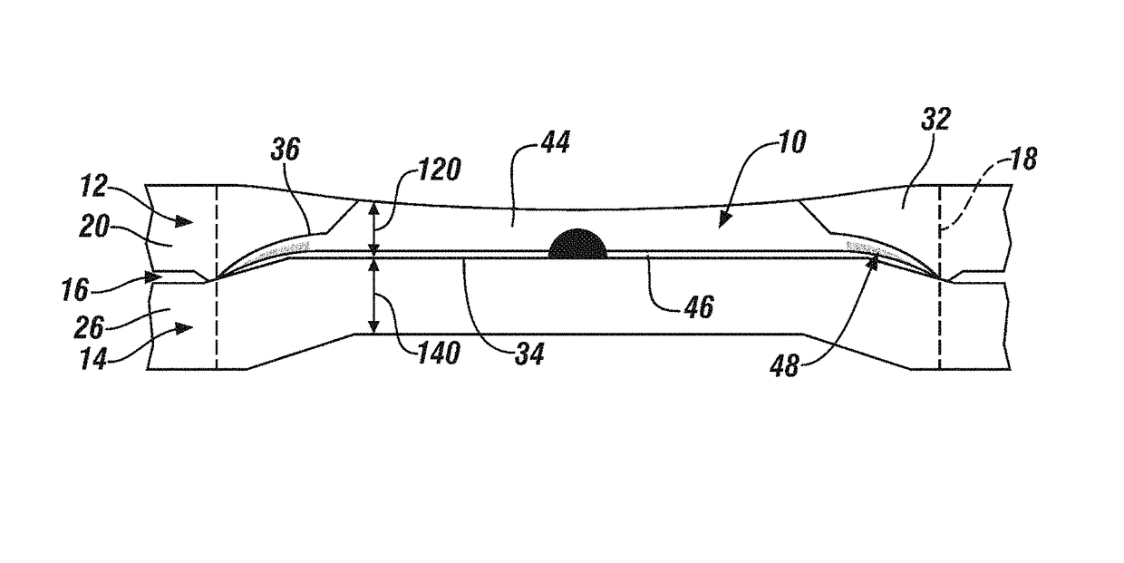
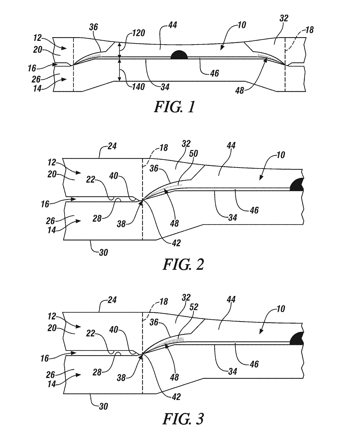
[0034]Spot welding an aluminum workpiece to a steel workpiece presents some notable challenges. In fact, as discussed above, several of the identified challenges that complicate the ability to spot weld those dissimilar metals relate to the susceptibility of the weld joint to being compromised at the interface of the joint and the faying surface of the steel workpiece by weld disparities, such as porosity and residual oxide fragments, and the presence of a hard and brittle intermetallic layer. These challenges are particularly problematic when an intermediate organic material is present between the two workpieces at the faying interface because the organic material can interact with a residual oxide film to form a more mechanically tough composite residue film. A weld joint 10 is disclosed here that counteracts at least some of the accumulation of weld joint disparities at and along a bonding interface of the weld joint 10 and the steel workpiece and, additionally, protects the bond...


PUM

PropertyMeasurementUnit
Thicknessaaaaaaaaaa
Thicknessaaaaaaaaaa
Thicknessaaaaaaaaaa

Abstract

A weld joint is disclosed that weld bonds together an aluminum workpiece and a steel workpiece. The weld joint includes an aluminum weld nugget, an intermetallic layer, and an annular ring of aluminide particles that is selected from the group consisting of nickel aluminide particles, iron aluminide particles, and a combination thereof. The annular ring of aluminide particles extends upwards from a weld bond surface of the weld joint such that the annular ring of aluminide particles extends radially inwardly into the aluminum weld nugget and protects the weld bond surface of the weld joint against crack propagation that may originate from a notch root of the weld joint.

Description

CROSS-REFERENCE TO RELATED APPLICATION(S)[0001]This application claims the benefit of U.S. Provisional Application No. 62 / 319,846 filed on Apr. 8, 2016. The entire contents of the aforementioned provisional application are incorporated herein by reference in its entirety.TECHNICAL FIELD[0002]The technical field of this disclosure relates generally to a weld joint that bonds an aluminum workpiece and a steel workpiece together within a weld zone.INTRODUCTION[0003]Resistance spot welding is a process used by a number of industries to join together two or more metal workpieces. The automotive industry, for example, often uses resistance spot welding to join together metal workpieces during the manufacture of vehicle structural frame members (e.g., body sides and cross members) and vehicle closure members (e.g., vehicle doors, hoods, trunk lids, and lift gates), among others. A number of spot welds are often formed at various points around a peripheral edge of the metal workpieces or so...

Claims


Application Information

Patent Timeline
IPC IPC(8): B23K11/20B23K11/18F16B5/08
CPCB23K11/20B23K11/185F16B5/08B23K33/00B23K2103/20B23K11/115
Inventor SIGLER, DAVIDCARLSON, BLAIRMADDELA, SURENDER
Owner HUAMI INC
Why Eureka
Try Eureka