
Apparatus for controlling internal combustion engine

a technology of internal combustion engine and actuator, which is applied in the direction of electric control, machines/engines, output power, etc., can solve the problems of ineffective significant pumping losses, and achieve the effect of reducing flow losses, suppressing energy consumption required by the operation of compression release mechanisms, and facilitating utilization of inertial energy

Active Publication Date: 2017-10-12
TOYOTA JIDOSHA KK
View PDF9 Cites 3 Cited by
  • Summary
  • Abstract
  • Description
  • Claims
  • Application Information

AI Technical Summary

Benefits of technology

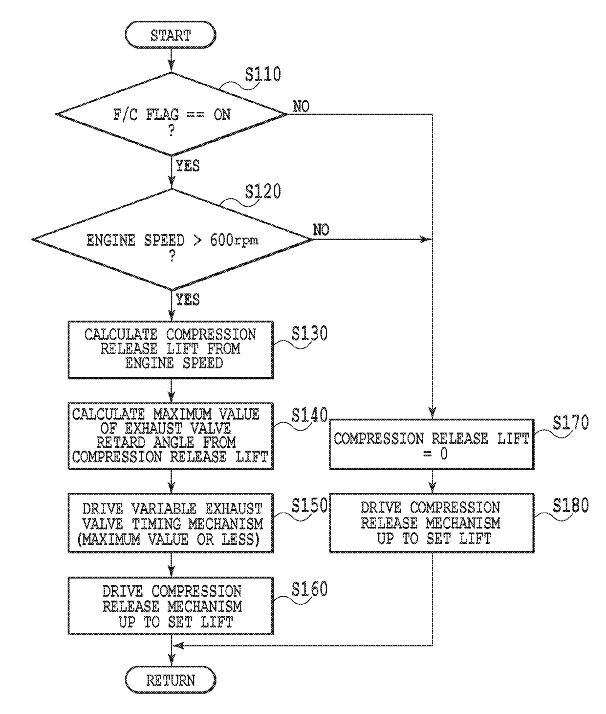
The present invention aims to improve engine performance by reducing pumping losses and energy consumption during high engine speed operations, while also facilitating the efficient utilization of inertial energy. This is achieved through the control of a compression release mechanism that adjusts its opening degree based on the engine speed. By increasing the valve opening degree during coasting with the fuel cut off, the energy consumption required by the operation of the compression release mechanism may be suppressed, while in the region of high speed, flow losses may be decreased to suppress pumping losses. Additionally, by minimizing the difference in power loss between when the compression release mechanism is operating and not operating, a lessened sense of deceleration caused by the operation of the compression release mechanism may be minimized, while also making it possible to facilitate power generation by the electric generator.

Problems solved by technology

However, if the valve opening degree of the compression release mechanism is small while coasting with the fuel cut off, significant pumping losses occur in the region of high engine speed, and inertial energy cannot be utilized effectively.

Method used


Image

  • Apparatus for controlling internal combustion engine
  • Apparatus for controlling internal combustion engine
  • Apparatus for controlling internal combustion engine

Examples


first embodiment

[0082]Note that in the first embodiment, as illustrated in the engine speed—lift amount map of FIG. 8, in the region of less than a predetermined upper limit of the speed of the engine 1, the compression release lift amount Ld is predetermined to change proportionally and continuously with respect to changes in engine speed. For this reason, shocks caused by changes in the compression release lift amount Ld may be suppressed. However, the relationship between the engine speed and the compression release lift amount Ld may also be predetermined so that the compression release lift amount Ld changes in a stepwise or discrete manner in multiple stages (that is, two or more stages) as the engine speed increases gradually.

[0083]Next, a second exemplary embodiment of the present invention will be described.

[0084]Engines having an additional mechanism to vary the opening / closing phases of not only intake valves but also the exhaust valves are widely used. The purposes of such a mechanism a...

second embodiment

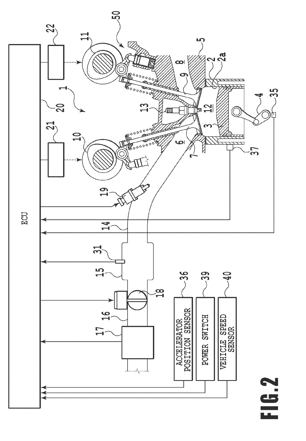
[0086]Such retardation of the closing timing of the exhaust valve may be maintained even when transitioning from normal driving, during which fuel is supplied, to coasting with the fuel cut off. Also, even when coasting with the fuel cut off, it is still conceivable to retard the closing timing of the exhaust valve 9 in order to decrease pumping losses, increase inertial travel distance, and / or increase the amount of regenerated electric power to decrease fuel consumption. However, in the case of a compression release mechanism that provides an additional opening degree to the exhaust valve 9, there is a risk that providing the compression release lift amount Ld will cause the lift amount in the maximally retarded case to take the dashed line h2, and the exhaust valve 9 to interfere with the piston 3. For this reason, in order to avoid interference between the exhaust valve 9 and the piston 3, a sufficiently large compression release lift amount Ld cannot be set. On the other hand, ...

third embodiment

[0097]Next, the present invention will be described.

[0098]In the foregoing first embodiment, when coasting with the fuel cut off, the compression release lift amount Ld of the exhaust valve 9 is made larger as the speed of the engine 1 rises. For this reason, in the region of high speed, pumping losses caused by flow losses may be suppressed, and engine friction may be suppressed. However, there is a problem in that, even though the engine speed is in the high region, there is little sense of deceleration caused by the engine deceleration torque, which may feel unnatural to the driver. The third embodiment is directed at this problem, and features controlling the deceleration torque produced by the generator according to the difference in power loss between when the compression release mechanism 50 is operating and not operating.

[0099]In the third embodiment, the deceleration torque of the second motor generator MG2 is made to increase to compensate for the decrease in engine decele...


PUM


Abstract

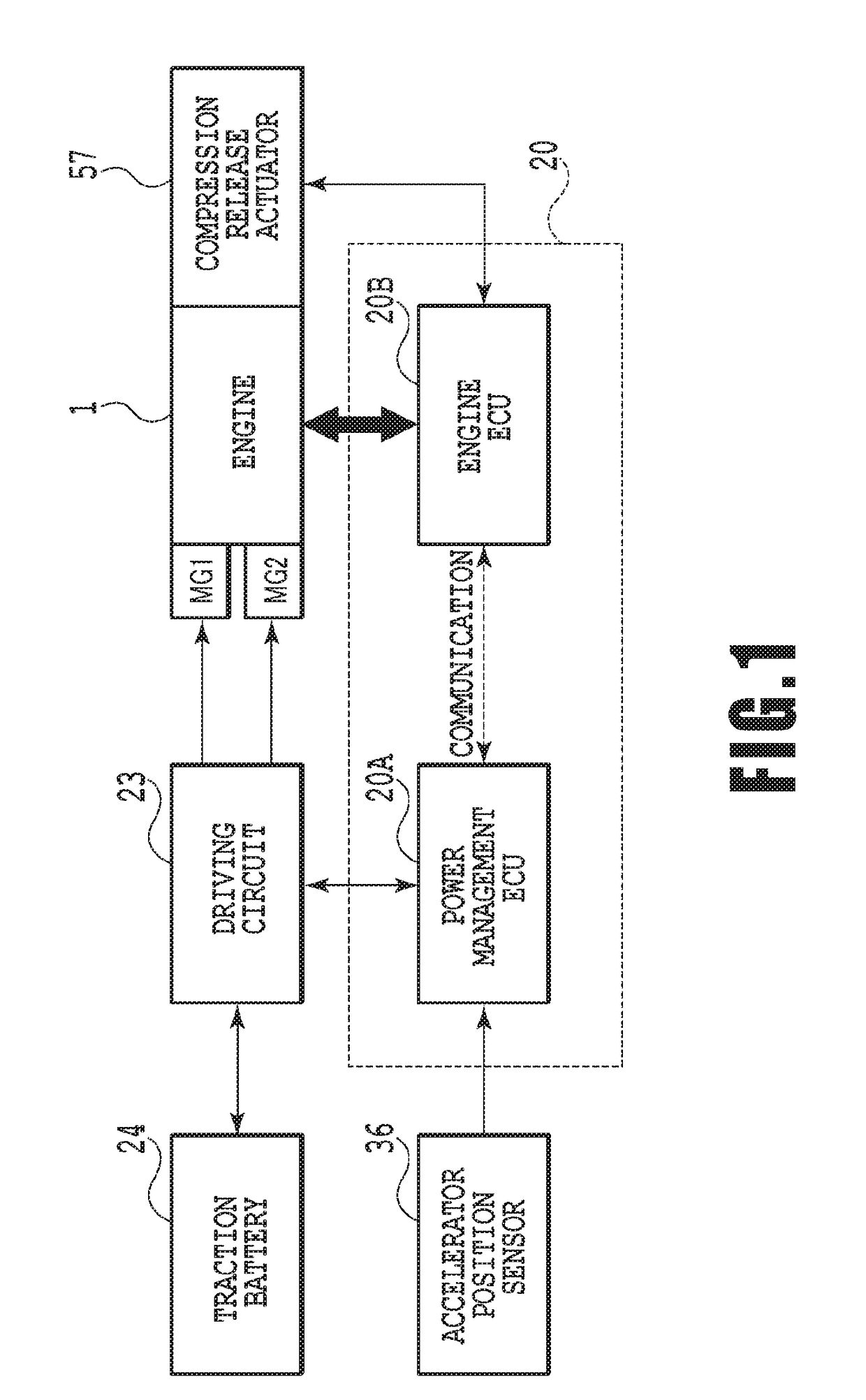
An apparatus for controlling an internal combustion engine is provided. An engine includes a compression release mechanism and a fuel injection valve. The compression release mechanism variably controls the opening degree of a valve member, and thereby connects the combustion chamber of the engine with at least one of the intake passage and the exhaust passage in order to release in-cylinder pressure during at least the compression stroke. A controller controls the fuel injection valve to execute coasting with the fuel cut off in which the fuel is cut off under a predetermined condition, and while executing coasting with the fuel cut off, controls the compression release mechanism to increase the opening degree of the valve member of the compression release mechanism as the speed of the engine is higher.

Description

TECHNICAL FIELD[0001]The present invention relates to an apparatus for controlling an internal combustion engine, and more particularly, to an apparatus that controls an internal combustion engine equipped with a compression release mechanism for releasing in-cylinder pressure.BACKGROUND ART[0002]An internal combustion engine equipped with a compression release mechanism (or decompressor) that connects the combustion chamber with an intake passage and / or an exhaust passage during a compression stroke is commonly known. According to such a compression release mechanism, in-cylinder pressure is released during startup or when coasting with the fuel cut off, thereby reducing the load on the startup motor during startup, and also suppressing deceleration shock when starting coasting with the fuel cut off.[0003]One type of compression release mechanism controls the lift amount of an intake valve and / or an exhaust valve, so as to put the intake valve and / or the exhaust valve into a consta...

Claims


Application Information

Patent Timeline
IPC IPC(8): F02D13/02F02D41/12F02B63/04F02D41/26F02D41/30B60L50/16
CPCF02D13/0215F02D41/26F02D41/123F02B63/04F02D41/3005F02D2041/001
Inventor NISHIDA, HIDEYUKIKOBAYASHI, TATSUO
Owner TOYOTA JIDOSHA KK
Learn More