Combustor assembly for low-emissions and alternate liquid fuels

Active Publication Date: 2017-10-12
UNIVERSITY OF ALABAMA
View PDF2 Cites 1 Cited by
  • Summary
  • Abstract
  • Description
  • Claims
  • Application Information

AI Technical Summary

Benefits of technology

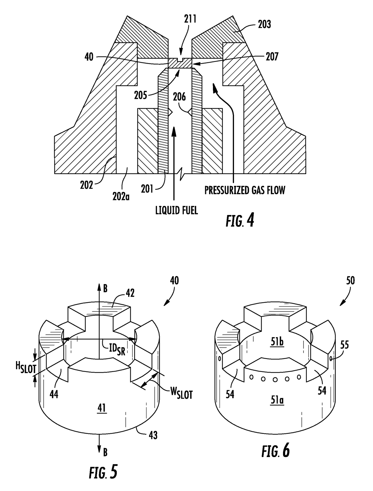
[0007]Various implementations include a fuel injector that includes an inner injector tube, an outer injector tube, a spacer ring, and an orifice plate. The inner injector tube includes an outlet portion defining an outlet and a choke portion. The choke portion is disposed below the outlet 10 D to 20 D, wherein D is the inner tube diameter. The outer injector tube is spaced radially apart from at least the outlet portion of the inner injector tube. The outer injector tube has an outer injector tube outlet disposed radially adjacent the outlet of the inner injector tube. The spacer ring includes an annular wall that d

Problems solved by technology

Most combustion applications have limited fuel flexibility mainly because of the strong dependence of the injector performance on physical and chemical properties of the fuel.
However, a major shortcoming of this technique is that in highly viscous liquids such as glycerol or straight vegetable oils, or other alternative and opportunity fuels, shear layer instabilities are suppressed, giving rise to less effective droplet break up or l

Method used


Image

  • Combustor assembly for low-emissions and alternate liquid fuels
  • Combustor assembly for low-emissions and alternate liquid fuels
  • Combustor assembly for low-emissions and alternate liquid fuels

Examples


Example

[0025]According to various implementations, a combustor assembly is described that yields low emissions, requires low pumping power, is suitable for conventional and alternate liquid fuels, including highly viscous processed or unprocessed fuels, and can be scaled to different heat release rates. The combustor assembly according to certain implementations includes a FB injector.

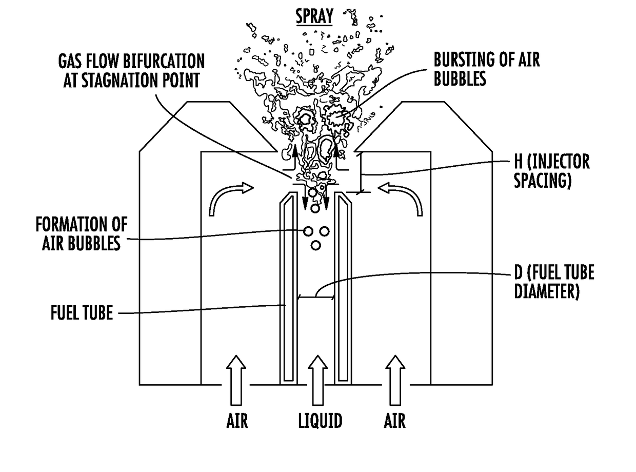
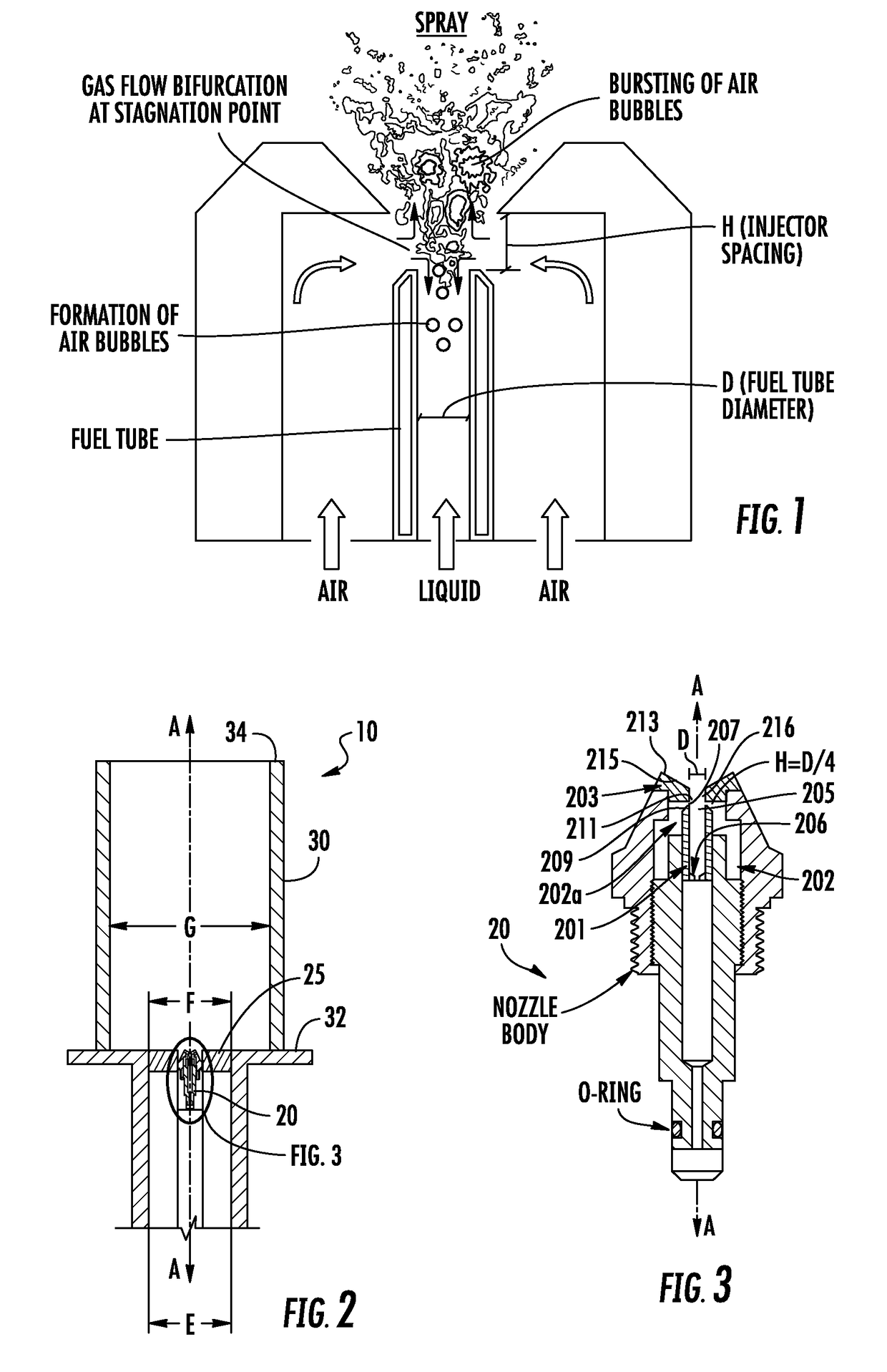
[0026]A twin-fluid atomization technique known as Flow Blurring (FB) atomization was recently proposed by A.M. Gañán-Calvo. This technique is reported to produce finer droplets with up to fifty times the surface area to volume ratio and atomization efficiency of tenfold when compared to AB atomization. FIG. 1 shows a schematic illustration of FB atomization's working principle. Atomizing gas is forced through a small gap between an exit of the liquid tube and a coaxial orifice located at distance “H” downstream of the exit of the liquid tube. For H / D of 0.25 or less (wherein D is the orifice diameter), the at...


PUM


Abstract

Implementations of a combustor assembly yield low emissions, require low power, are suitable for alternate liquid fuels, including highly viscous fuels, and are scalable for various heat release rates. The combustor assembly includes a fuel injector and a swirler. The fuel injector may include a choke portion and a spacer. The choke portion is disposed just upstream of an outlet of a liquid fuel conduit and prevents atomizing gas from interrupting continuous flow of the liquid fuel through the liquid fuel conduit. The spacer is disposed downstream of the outlet to precisely control the gap and thus, bifurcation of atomizing gas flow, between the outlet of liquid fuel conduit and an inlet of an orifice plate. The swirler is disposed radially outwardly and adjacent the fuel injector and includes a plurality of angled vanes.

Description

CROSS-REFERENCE TO RELATED APPLICATIONS[0001]This application claims priority to U.S. Provisional Patent Application No. 62 / 321,288, filed Apr. 12, 2016, and entitled “COMBUSTOR ASSEMBLY FOR LOW-EMISSIONS AND ALTERNATE LIQUID FUELS,” the entire disclosure of which is incorporated herein by reference.STATEMENT REGARDING FEDERALLY SPONSORED RESEARCH OR DEVELOPMENT[0002]This invention was made with government support under grant no. DE-EE0001733 awarded by the Department of Energy. The government has certain rights in the invention.BACKGROUND OF THE INVENTION[0003]Fluctuating fuel prices, unabated energy sustainability concerns, and waste energy byproducts generated in industry have created the opportunity to develop fuel flexible combustion systems. A combustion system's capability to handle multiple liquid fuels depends on the fuel injector. Most combustion applications have limited fuel flexibility mainly because of the strong dependence of the injector performance on physical and c...

Claims


Application Information

Patent Timeline
IPC IPC(8): F23D11/10F23D11/38F23D11/14
CPCF23D11/107F23D11/383F23D11/14F23C7/004F23D11/101F23D11/38F23D17/002
Inventor AGRAWAL, AJAY K.
Owner UNIVERSITY OF ALABAMA
Why Eureka
Try Eureka