Outer cup rotary axial eddy current damper

a rotary axial eddy current and damper technology, which is applied in the direction of mechanical equipment, asynchronous induction clutches/brakes, and direct use of axial relative motion modes. it is difficult for the rotating disk structure therein to meet the speed index requirement of less than 1 and achieves the effect of improving the anti-vibration control effect of reducing the axial eddy current damper efficiency index, and convenient adjustment of maximum working speed

Active Publication Date: 2017-10-12
HUNAN XIAOZHEN ENG TECH CO LTD
View PDF0 Cites 8 Cited by
  • Summary
  • Abstract
  • Description
  • Claims
  • Application Information

AI Technical Summary

Benefits of technology

[0021]2) The damper makes full use of the mass moments of inertia of rotational motion components in the rotary eddy current damping generators, and thus a significant negative stiffness effect can be formed, thereby further improving the anti-vibration control effect of the axial eddy current damper.
[0022]3) The damper can conveniently adjust the maximum working speeds of the individual eddy current damping generators by the damping force dampers, simulate a nonlinear damper with a speed index of less than 1 by the plurality of eddy current damping generators, and have the same damping force-speed working characteristics as the viscous fluid damper; in addition, the eddy current damper has an allowable maximum working speed much higher than that of the viscous fluid damper.
[0023]4) The damper can have its working stroke increased by increasing only the length of the screw rod, whereas the increase of the stroke requires a little cost is to be increased. In contrast, it is necessary for the viscous fluid damper to increase both the length of the piston rod and the length of the cylinder to increase the working stroke of the damper, which makes a large-stroke viscous fluid damper quite expensive.
[0024]5) The damper can have its damping coefficient increased by three ways of increasing diameters of the stator and the rotor, increasing the magnetic field strength of the magnets and increasing the number of the magnets, and it is suitable for manufacture of various dampers of a large, medium or small size.
[0025]6) The screw set drive used by the damper is a standard mechanical drive mode, thus it is easy for the present damper to make standardized mass production thereof come true.
[0026]7) Semi-active control can be realized by use of an electric magnetic, which makes the damper simpler in structure and lower in cost than a magneto-rheological damper.

Problems solved by technology

If being connected with a vibrating structure, the conductor plate may produce effects of structural damping and energy dissipation, forming an eddy current damper.
Different from some damping devices commonly used in the field of structural vibration control, the eddy current damper dissipates energy without using mechanical friction, and here problems of fluid leakage and sealing do not occur since no working fluid is used; furthermore, it has advantages such as high reliability, excellent durability and relatively simple structure, and is therefore particularly suitable for use in a working environment requiring a long fatigue life and being not easy for maintenance.
The eddy current damping itself has a low energy dissipation density, and thus causes the efficiency index of the eddy current damper directly using an axial relative motion mode to be low, which is the main reason why the eddy current damping is hindered from being applied to large-scale engineering structures for a long time.
The Chinese Patent Application with Publication Number of CN103821861A greatly improves the efficiency index of the eddy current damper by use of screw drive, however, it is difficult for the rotating disk structure therein to meet an anti-vibration requirement for a speed index of less than 1.

Method used


Image

  • Outer cup rotary axial eddy current damper
  • Outer cup rotary axial eddy current damper
  • Outer cup rotary axial eddy current damper

Examples


Embodiment Construction

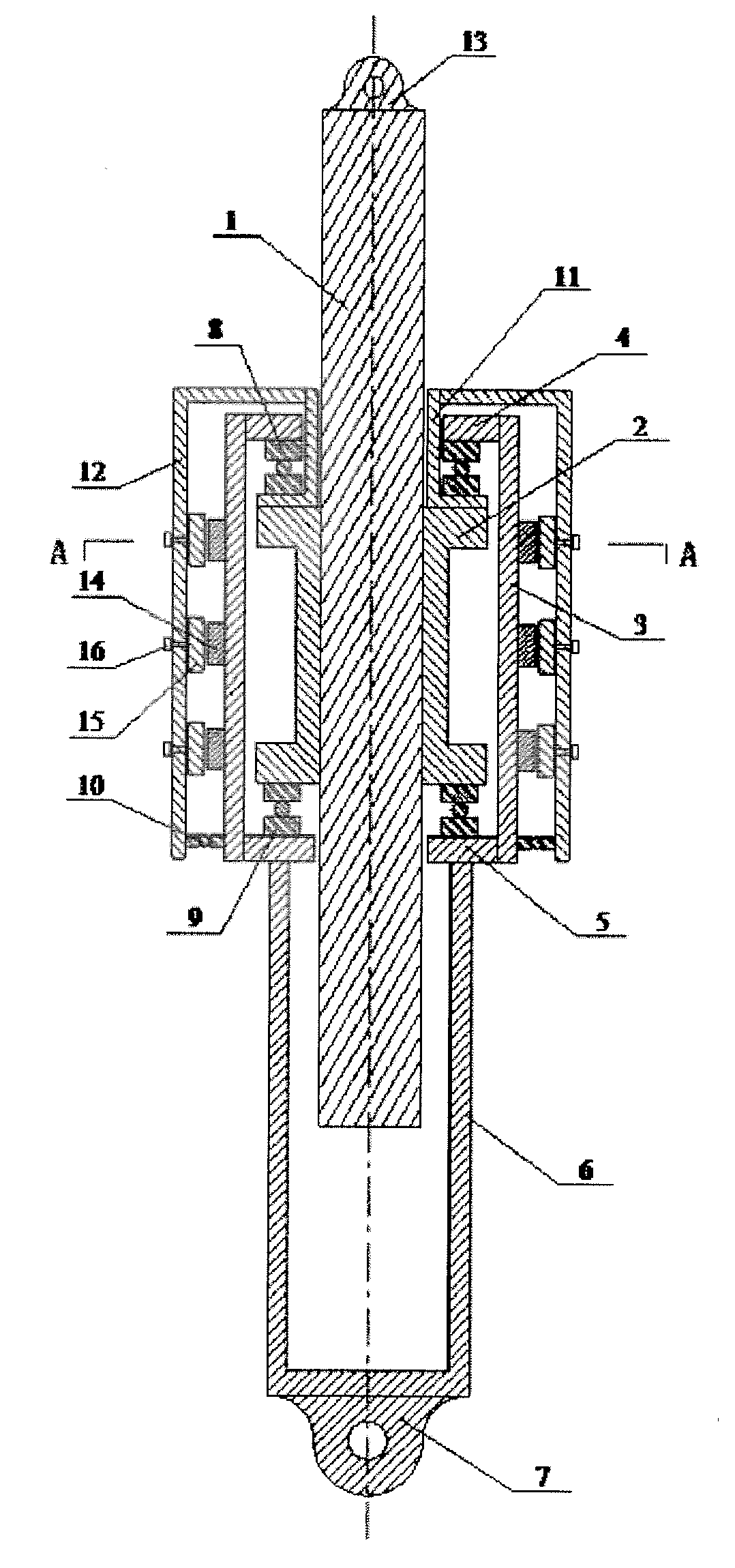
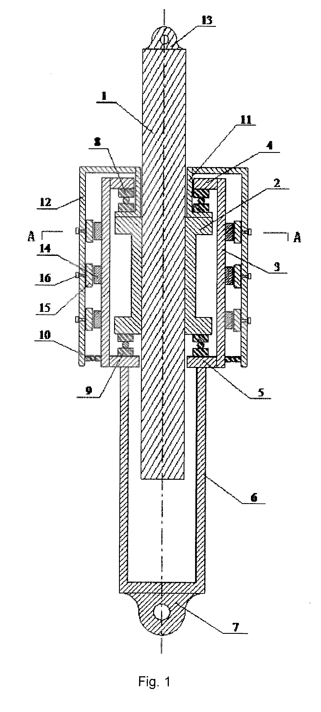
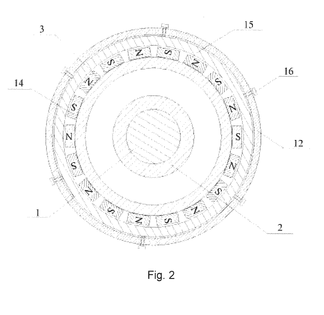
[0029]As shown in FIG. 1, an outer cup rotary axial eddy current damper includes a drive assembly and eddy current damping generators. The drive assembly includes a screw drive set, and a stator and a rotor respectively made of magnetic conductive materials. The screw drive set includes a screw rod 1 and a nut 2 sleeved on the screw rod 1. The stator 3 is a circular tube with an upper opening and a lower opening. An upper flange 4 is mounted at the upper opening of the stator 3, and a lower flange 5 is mounted at the lower opening of the stator 3. The screw rod 1 sequentially passes through a central hole of the upper flange 4 and a central hole of the lower flange 5. The nut 2 is arranged within the stator 3, with an upper end surface of the nut 2 connected with a bottom surface of the upper flange 4 via an upper thrust bearing 8, and a lower end surface of the nut 2 connected with a top surface of the lower flange 5 via a lower thrust bearing 9. The rotor includes an outer rotor 1...


PUM


Abstract

A large-size axial eddy current damper manufactured by use of screw drive comprises a drive assembly and an eddy current damping generator; the drive assembly comprises a screw drive pair, and a stator and a rotor respectively made of magnetic conductive materials; the screw drive pair comprises a screw rod and a nut sleeved on the screw rod; the screw rod sequentially penetrates through central holes of upper and lower flanges of the stator; the nut is within the stator; the rotor comprises an outer rotor and an inner rotor having the bottom provided with a lower connecting flange; one or more eddy current damping generators are arranged between the stator and the outer rotor. Problems of having difficulty in manufacturing axial dampers with a large damping coefficient and simulating anti-vibration dampers with a speed index of less than 1, by use of eddy current damping, can be solved simultaneously.

Description

TECHNICAL FIELD[0001]The present invention relates to a large-size axial eddy current damper manufactured by use of screw drive.BACKGROUND ART[0002]Eddy current damping is generated in accordance with the basic principle in which when a conductor plate in a local magnetic field cuts magnetic lines of force, eddy current is generated in the conductor plate, and the eddy current in turn generates a new magnetic field having a direction opposite to that of the original magnetic field, and thus a damping force, which hinders a relative motion of the original magnetic field and the conductor plate, is formed therebetween, and meanwhile, under a resistance effect of the conductor plate, kinetic energy obtained by the conductor plate is converted by means of the eddy current into heat energy for dissipation. If being connected with a vibrating structure, the conductor plate may produce effects of structural damping and energy dissipation, forming an eddy current damper. Different from some...

Claims


Application Information

Patent Timeline
Patent Type & Authority Applications(United States)
IPC IPC(8): H02K49/04
CPCH02K49/043F16F15/035F16F2232/06H02K16/02H02K7/06F16H25/20F16F6/005
Inventor CHEN, ZHENGQING
Owner HUNAN XIAOZHEN ENG TECH CO LTD
Why Eureka
Try Eureka