Multiphase Coupled and Integrated Inductors with Printed Circuit Board (PCB) Windings for Power Factor Correction (PFC) Converters

a technology of power factor correction and integrated inductors, which is applied in the direction of power conversion systems, climate sustainability, basic electric elements, etc., can solve the problems of increasing the switching frequency substantially increasing the switching power loss, the topology of the boost pfc converter is complex, and the cost of production is more expensive than other pfc converter topologies, so as to reduce the average switching frequency, reduce the loss of non-zvs, and reduce the effect of switching loss

a technology of power factor correction and integrated inductors, which is applied in the direction of power conversion systems, climate sustainability, basic electric elements, etc., can solve the problems of increasing the switching frequency substantially increasing the switching power loss, the topology of the boost pfc converter is complex, and the cost of production is more expensive than other pfc converter topologies, so as to reduce the average switching frequency, reduce the loss of non-zvs, and reduce the effect of switching loss

US20170294833A1Active Publication Date: 2017-10-12VIRGINIA TECH INTPROP INC

Image

  • Multiphase Coupled and Integrated Inductors with Printed Circuit Board (PCB) Windings for Power Factor Correction (PFC) Converters
  • Multiphase Coupled and Integrated Inductors with Printed Circuit Board (PCB) Windings for Power Factor Correction (PFC) Converters
  • Multiphase Coupled and Integrated Inductors with Printed Circuit Board (PCB) Windings for Power Factor Correction (PFC) Converters

Examples


Embodiment Construction

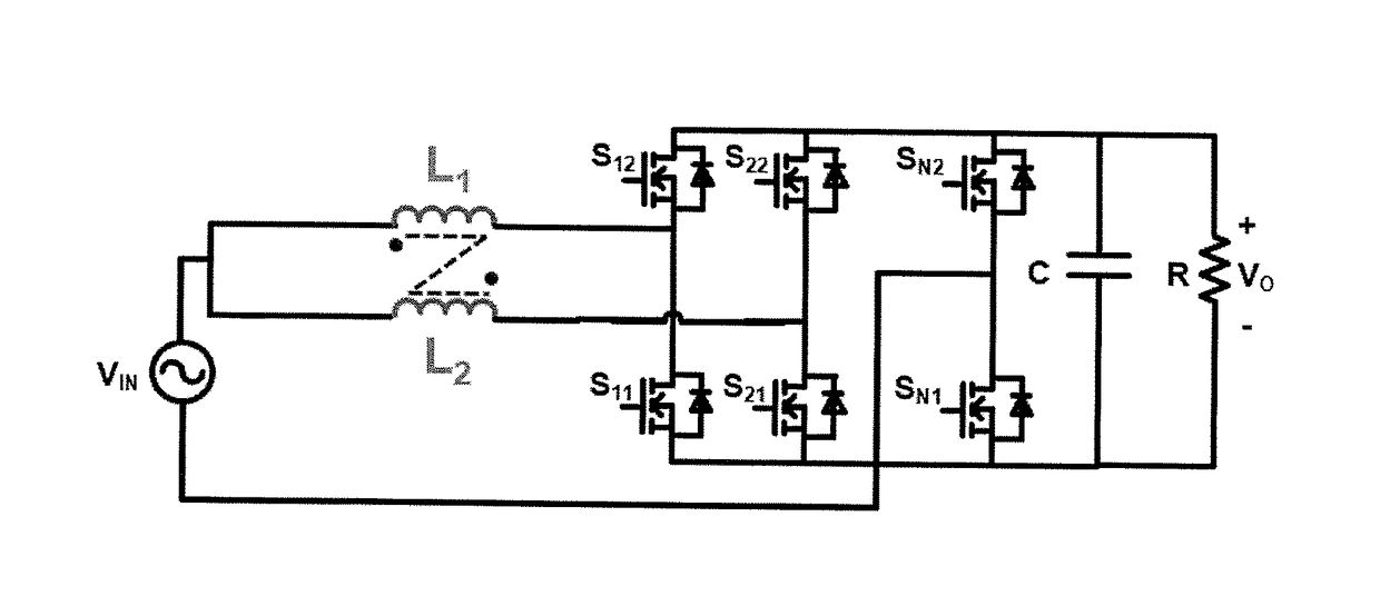
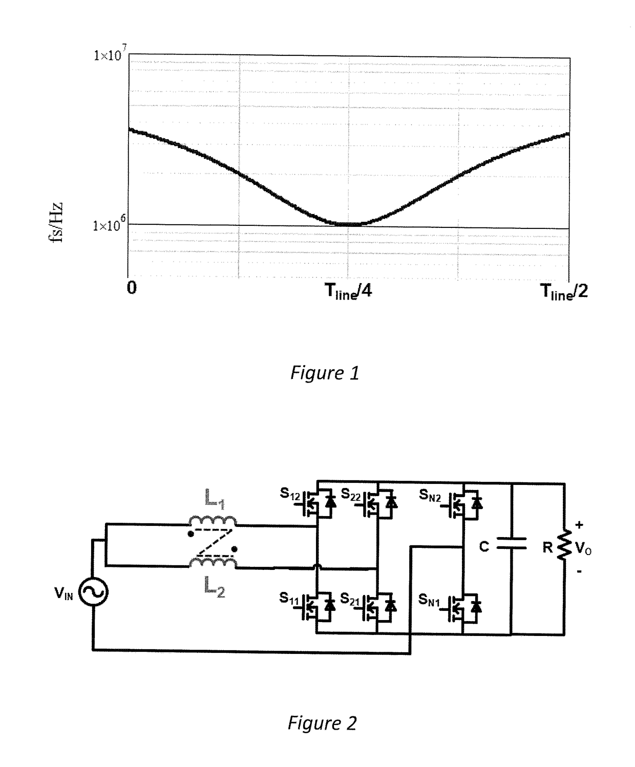
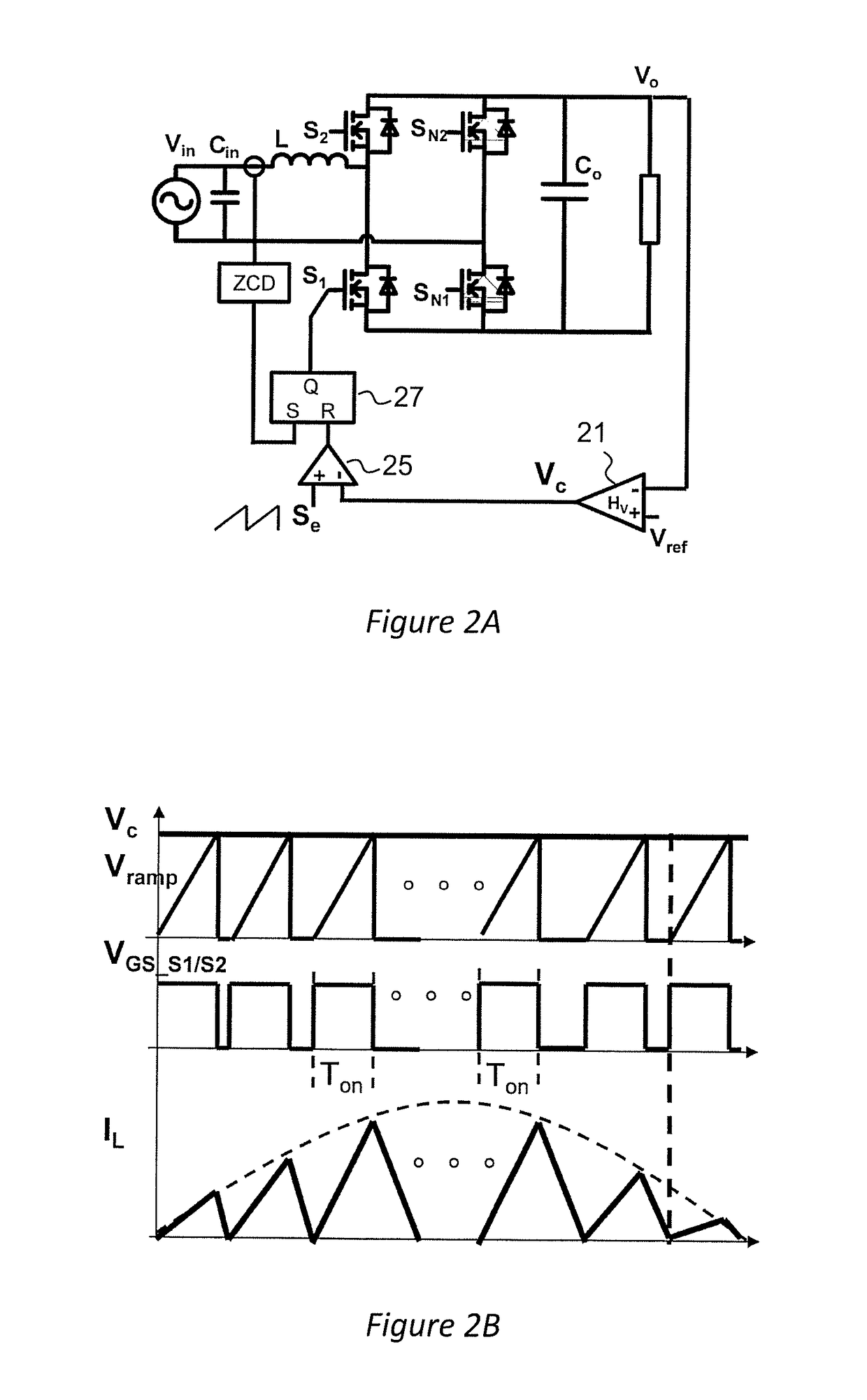
[0043]Referring now to the drawings, and more particularly to FIG. 1, there is shown a graph of the switching frequency of a CRM totem-pole PFC converter over a half line cycle of input voltage. The operating principle of CRM PFC converters, regardless of converter topology, is well-known. Ideally, when a switch is closed to draw power from the input power source, the inductor current will increase substantially linearly. When the switch is turned off, for example, after a fixed time period in a so-called constant on-time (COT) mode of operation, the inductor current will decrease substantially linearly. When the inductor current reaches zero, the switch is again turned on and the switching cycle is repeated. Thus, the inductor current will ideally be a series of triangular waves with a variable maximum current given by

ipk=(Vin / L)*Tonā€ƒā€ƒ(1)

which varies with the sinusoidal variation of input voltage and a minimum current of zero. Due to the substantial linearity of the increase and de...


PUM

PropertyMeasurementUnit
equivalent inductanceaaaaaaaaaa
inductanceaaaaaaaaaa
inductancesaaaaaaaaaa

Abstract

A power factor correction (PFC) power converter, particularly of a multiphase totem-pole or other topology presenting a switching bridge that can potentially provide bi-directional power transfer control, reduces a nominal switching frequency and achieves zero voltage switching over an increased portion of a half line cycle by providing positive or inverse coupling of inductors in an inductor structure that can be formed of a multi-layer printed circuit board such that at least three different inductances are presented during each half line cycle period; allowing increased switching frequency and simplifying EMI filtering arrangements. Parasitic capacitances can be balanced with additional coupled windings to reduce differential mode and common mode noise. The PFC power converter is particularly applicable to provide bi-directional power control from an on-board battery charger in an electrically powered vehicle.

Description

CROSS-REFERENCE TO RELATED APPLICATIONS[0001]This application claims benefit of priority of U.S. Provisional Application 62 / 321,250, filed Apr. 12, 2016, which is hereby incorporated by reference in its entirety.FIELD OF THE INVENTION[0002]The present invention generally relates to high-efficiency direct and inverse coupled multiphase inductor structures suitable for being fabricated with printed circuit board (PCB) windings, particularly for use in high power density power factor correction (PFC) power converters and which reduce or eliminate common mode (CM) noise reflection to the power source.BACKGROUND OF THE INVENTION[0003]A power factor correction (PFC) converter is an essential component of power converter structures that derive power from an alternating current (AC) source such as the power distribution network or grid. The power factor correction function serves to prevent phase changes due to variation in load current from being reflected to the AC source and to maintain ...

Claims


Application Information

Patent Timeline
12 Oct 2017
Publication
US20170294833A1
IPC
H02M1/42; H01F27/28; H02M1/084
CPC
H02M1/42; H01F2027/2809; H01F27/2804; H02M1/084; H02M1/4225; H02M7/23; Y02B70/10
Inventors
YANG, YUCHEN; MU, MINGKAI