
Fiber communication systems and methods

a fiber communication and fiber technology, applied in the field of fiber communication networks, can solve the problems of low receiver sensitivity, significant engineering complexity, and low sensitivity of current detection scheme wdm technology, and achieve the effects of reducing the cost of operation, and increasing the complexity of the system

Active Publication Date: 2017-10-12
CABLE TELEVISION LAB
View PDF0 Cites 55 Cited by
  • Summary
  • Abstract
  • Description
  • Claims
  • Application Information

AI Technical Summary

Benefits of technology

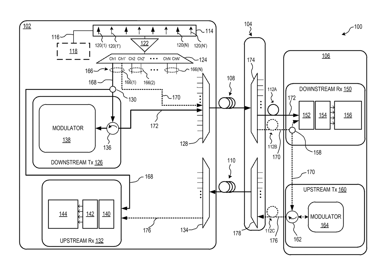
The patent text describes an injection locked transmitter system for optical communication networks. The system includes a master seed laser source, an input data stream, and a laser injected modulator with a slave laser. The laser injected modulator receives the master seed laser source input and data stream and outputs a modulated data stream. The patent also describes an optical network communication system that includes an optical frequency comb generator and transmitter for generating coherent toned signals. The system further includes a receiver for receiving the coherent toned signals and utilizing them for downstream heterodyne detection. The patent also describes a method of optical network processing involving generating coherent tones, transmitting them to a receiver, and using them for downstream heterodyne detection by optical multiplexing. The technical effects of the patent text are improved transmission of optical data over optical communication networks and improved coherent detection techniques.

Problems solved by technology

Current detection scheme WDM technology, however, is limited by its low receiver sensitivity, and also by the few options available to upgrade and scale the technology, particularly with regard to use in conjunction with the lower-quality legacy fiber environment.
Long distance transmission using coherent technology, however, requires elaborate post-processing, including signal equalizations and carrier recovery, to adjust for impairments experienced along the transmission pathway, thereby presenting significant challenges by significantly increasing system complexity.
However, these modules still require significant engineering complexity, expense, size, and power to operate, and therefore have not been efficient or practical to implement in access applications.

Method used


Image

  • Fiber communication systems and methods
  • Fiber communication systems and methods
  • Fiber communication systems and methods

Examples


Embodiment Construction

[0023]In the following specification and the claims, reference will be made to a number of terms, which shall be defined to have the following meanings.

[0024]The singular forms “a,”“an,” and “the” include plural references unless the context clearly dictates otherwise.

[0025]“Optional” or “optionally” means that the subsequently described event or circumstance may or may not occur, and that the description includes instances where the event occurs and instances where it does not.

[0026]Approximating language, as used herein throughout the specification and claims, may be applied to modify any quantitative representation that could permissibly vary without resulting in a change in the basic function to which it is related. Accordingly, a value modified by a term or terms, such as “about,”“approximately,” and “substantially,” are not to be limited to the precise value specified. In at least some instances, the approximating language may correspond to the precision of an instrument for m...


PUM


Abstract

An injection locked transmitter for an optical communication network includes a master seed laser source input substantially confined to a single longitudinal mode, an input data stream, and a laser injected modulator including at least one slave laser having a resonator frequency that is injection locked to a frequency of the single longitudinal mode of the master seed laser source. The laser injected modulator is configured to receive the master seed laser source input and the input data stream, and output a laser modulated data stream.

Description

CROSS REFERENCE TO RELATED APPLICATIONS[0001]This application claims the benefit of and priority to U.S. Provisional Patent Application Ser. No. 62 / 321,211, filed Apr. 12, 2016, which is incorporated herein by reference in its entirety.BACKGROUND[0002]The field of the disclosure relates generally to fiber communication networks, and more particularly, to optical networks utilizing wavelength division multiplexing.[0003]Telecommunications networks include an access network through which end user subscribers connect to a service provider. Bandwidth requirements for delivering high-speed data and video services through the access network are rapidly increasing to meet growing consumer demands. At present, data delivery over the access network is growing by gigabits(Gb) / second for residential subscribers, and by multi-Gb / s for business subscribers. Present access networks are based on passive optical network (PON) access technologies, which have become the dominant system architecture t...

Claims


Application Information

Patent Timeline
Patent Type & Authority Applications(United States)
IPC IPC(8): H04B10/50H04B10/532H04B10/63H04J14/04H04J14/06
CPCH04B10/504H04J14/04H04J14/06H04B10/505H04B10/532H04B10/502H04B10/63H04B10/506H04B10/503H04B10/64H04J14/0305
Inventor JIA, ZHENSHENGCAMPOS, LUIS ALBERTOKNITTLE, CURTIS DEAN
Owner CABLE TELEVISION LAB
Learn More