Method for releasing a deployable boom

a technology of deployable booms and booms, which is applied in the field of deployable booms, can solve the problems of difficult or impossible application of the known methods of providing solar arrays described above to cubesats, the limitations of the common approach in how compact arrays can be packaged, and the limited superstructure of flexible membrane solar arrays

Active Publication Date: 2017-10-19
SOLAERO TECH CORP
View PDF4 Cites 10 Cited by
  • Summary
  • Abstract
  • Description
  • Claims
  • Application Information

AI Technical Summary

Benefits of technology

[0028]In some embodiments, the first and second sheets are deployed substantially simultaneously so that the first sheet is deployed in a first direction from the housing and the second sheet is deployed in an opposite direction from the housing. By using such an arrangement, which is described in greater detail below, the angular momentum imparted by deploying the first sheet can be canceled by the angu

Problems solved by technology

The common approach has limitations in how compactly the arrays can be packaged, because of the inherent volume and inflexibility of the rigid panels that are used as mounting substrates for the photovoltaic assemblies.
Such flexible membrane solar arrays with discrete and separate super-structures are limited in the shielding provided to the backside of the solar array after deployment, and by the complexity of deploying such an array with tensioning interfaces between the deployable boom and the nonstructural solar array blanket.
Although there is a desire to provide power for CubeSa

Method used


Image

  • Method for releasing a deployable boom
  • Method for releasing a deployable boom
  • Method for releasing a deployable boom

Examples


Embodiment Construction

[0049]Details of the present invention will now be described including exemplary aspects and embodiments thereof. Referring to the drawings and the following description, like reference numbers are used to identify like or functionally similar elements, and are intended to illustrate major features of exemplary embodiments in a highly simplified diagrammatic manner. Moreover, the drawings are not intended to depict every feature of the actual embodiment nor the relative dimensions of the depicted elements, and are not drawn to scale.

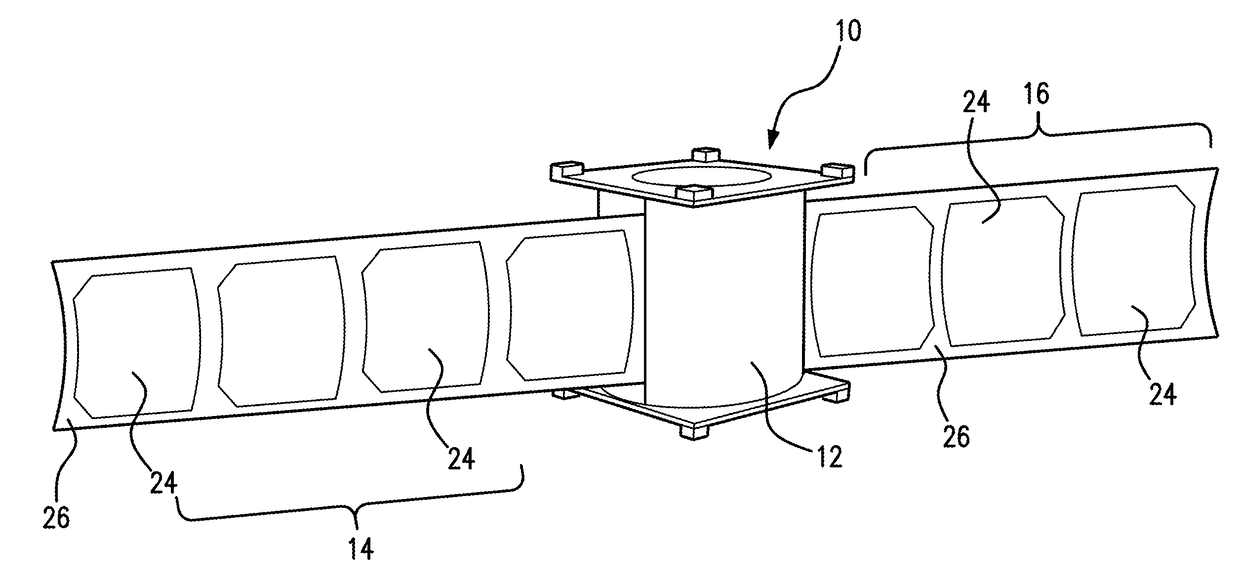
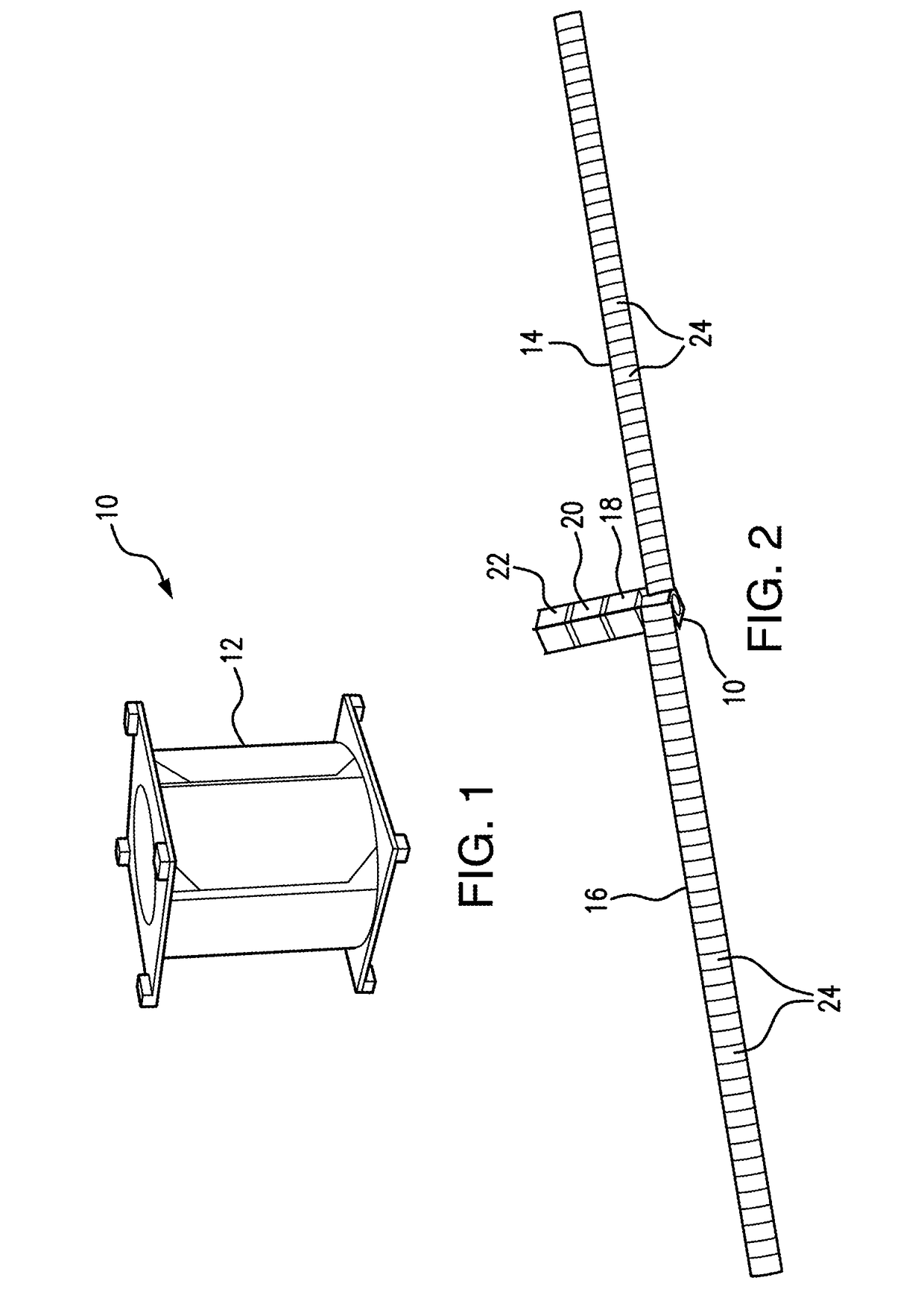
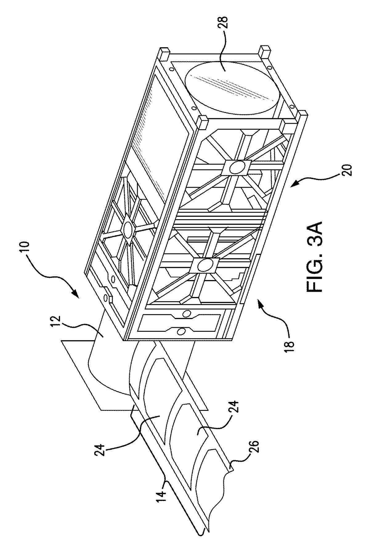
[0050]In the most general terms, the present disclosure relates to deployable booms associated with vehicles or permanent structures, the booms being structured components, or assemblies including, in some embodiments, transducers for collecting or emitting electromagnetic energy. One embodiment of the present disclosure depicts a space vehicle such as a satellite, in which the boom enables a compact stowed configuration of the deployable assembly during...


PUM


Abstract

The present disclosure describes a method of deploying an extensible boom from a housing. Sheets supporting respective arrays of photovoltaic devices are deployed substantially simultaneously so that a first sheet is deployed in a first direction from the housing and a second sheet is deployed in an opposite direction from the housing. Angular momentum imparted by deploying the first sheet is canceled by angular momentum imparted by deploying the second sheet. The housing can be part of a space satellite, such that the first and second sheets are deployed without causing the satellite to move out of its orbit.

Description

REFERENCE TO RELATED APPLICATIONS[0001]This application is a continuation-in-part of U.S. patent application Ser. No. 15 / 001,962, filed Jan. 20, 2016, which is a continuation-in-part of U.S. patent application Ser. No. 14 / 921,238, filed Oct. 23, 2015, which claims the benefit of U.S. Provisional Application No. 62 / 068,501 filed Oct. 24, 2014. The disclosures of the earlier applications are incorporated herein by reference in their entirety.[0002]This application is related to U.S. patent application Ser. No. 14 / 546,958, filed Nov. 18, 2014, now U.S. Pat. No. 9,004,410; and U.S. patent application Ser. No. 14 / 658,043, filed Mar. 13, 2015 now U.S. Pat. No. 9,079,673.BACKGROUND OF THE DISCLOSURE1. Field of the Disclosure[0003]The present disclosure relates to deployable booms associated with vehicles or permanent structures, the booms being structured components, or assemblies including, in some embodiments, transducers for collecting or emitting electromagnetic energy.2. Description o...

Claims


Application Information

Patent Timeline
IPC IPC(8): B64G1/44B64G1/22H01L31/042
CPCB64G1/443H01L31/042B64G1/222B64G1/44B64G1/66B65H75/28B65H2701/371H02S30/20B64G1/503Y02E10/50
Inventor STEELE, KENNETH LOYDSTERN, THEODORE GARRY
Owner SOLAERO TECH CORP
Why Eureka
Try Eureka