Substrate-loaded frequency-scaled ultra-wide spectrum element

a substrate-loaded, ultra-wide spectrum technology, applied in the field of ultra-wideband, single and phased array antennas, can solve the problems of limiting the beam steering increasing the total depth of the array, and affecting the performance of the antenna, so as to achieve good polarization, good impedance, and low cost

Active Publication Date: 2017-10-19
MITRE SPORTS INT LTD +1
View PDF1 Cites 24 Cited by
  • Summary
  • Abstract
  • Description
  • Claims
  • Application Information

AI Technical Summary

Benefits of technology

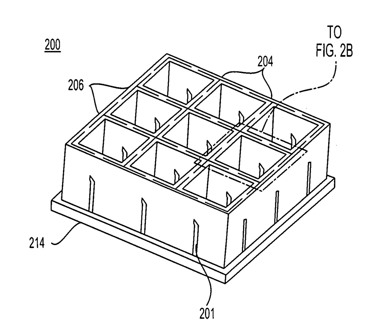
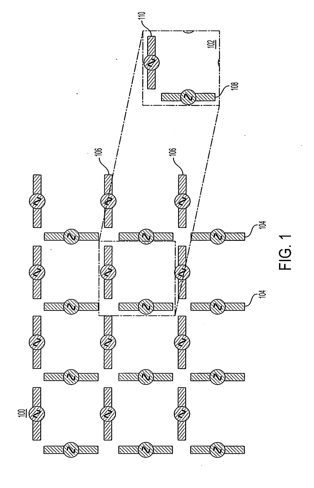
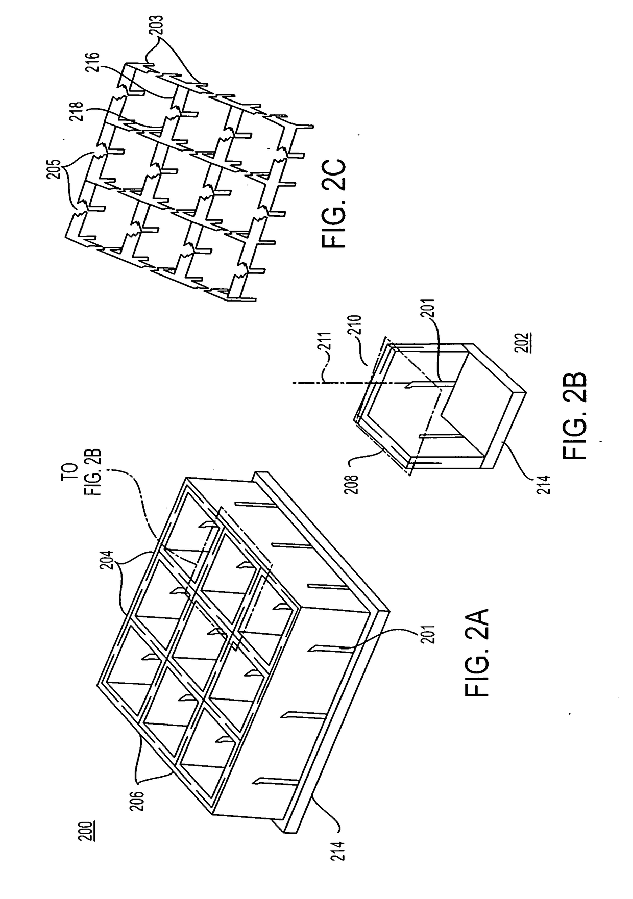
[0010]In accordance with some embodiments, a frequency scaled ultra-wide spectrum phased array antenna includes a pattern of unit cells of radiating elements and pillars formed into a metallic layers sandwiched between substrate layers. Each radiating element includes a signal ear and a ground ear. Radiating elements are configured to be electromagnetically coupled to one or more adjacent radiating elements via the pillars. The unit cells are scalable and may be combined into an array of any dimension to meet desired antenna performance. Embodiments can provide good impedance over ultra-wide bandwidth, wide scan angle, and good polarization, in a low cost, lightweight, small aperture design that is easy to manufacture.

Problems solved by technology

Phased array antennas for ultra-wide bandwidth (more than one octave bandwidth) performance are often large, causing excessive size, weight, and cost for applications requiring many elements.
The excessive size of an array may be required to accommodate “electrically large” radiating elements (several wavelengths in length), increasing the total depth of the array.
Grating lobes negatively impact a phased array antenna by dividing transmitted / received power into a main beam and false beams, creating ambiguous directional information relative to the main beam and generally limiting the beam steering performance of the antenna.
Phased array antenna design parameters such as antenna element size and spacing affect these performance characteristics, but the optimization of the parameters for the maximization of one characteristic may negatively impact another.
However, increased element length may negatively influence polarization and scan volume.
The scan volume can be increased through closer spacing of the antenna elements, but closer spacing can increase undesirable coupling between elements, thereby degrading performance.
This undesirable coupling can change rapidly as the frequency varies, making it difficult to maintain a wide bandwidth.
Existing wide bandwidth phased array antenna elements are often large and require contiguous electrical and mechanical connections between adjacent elements (such as the traditional Vivaldi).
In the last few years, there have been several new low-profile wideband phased array solutions, but many suffer from significant limitations.
Tightly coupled printed dipoles require superstrate materials to match the array at wide-scan angles, which adds height, weight, and cost.
Existing designs often have not been able to maximize phased array antenna performance characteristics such as bandwidth, scan volume, and polarization without sacrificing size, weight, cost, and / or manufacturability.

Method used


Image

  • Substrate-loaded frequency-scaled ultra-wide spectrum element
  • Substrate-loaded frequency-scaled ultra-wide spectrum element
  • Substrate-loaded frequency-scaled ultra-wide spectrum element

Examples


Embodiment Construction

[0058]In the following description of the disclosure and embodiments, reference is made to the accompanying drawings in which are shown, by way of illustration, specific embodiments that can be practiced. It is to be understood that other embodiments and examples can be practiced and changes can be made without departing from the scope of the disclosure.

[0059]In addition, it is also to be understood that the singular forms “a,”“an,” and “the” used in the following description are intended to include the plural forms as well, unless the context clearly indicates otherwise. It is also to be understood that the term “and / or” as used herein refers to and encompasses any and all possible combinations of one or more of the associated listed items. It is further to be understood that the terms “includes, “including,”“comprises,” and / or “comprising,” when used herein, specify the presence of stated features, integers, steps, operations, elements, components, and / or units, but do not preclud...


PUM


Abstract

A phased array antenna including a base plate and a board projecting from the base plate. The board including a dielectric layer and a conductive layer. The conductive layer includes first and second spaced apart radiating elements and a pillar disposed between the first and second spaced apart radiating elements. The pillar is electrically connected to the base plate, and the first and second spaced apart radiating elements are configured to capacitively couple to the pillar.

Description

CROSS-REFERENCE TO RELATED APPLICATIONS[0001]This application is related to the following application Ser. No.______, “Frequency-Scaled Ultra-Wide Spectrum Element,” filed Jun. 16, 2015, which is incorporated by reference herein in its entirety.STATEMENT REGARDING FEDERALLY SPONSORED RESEARCH OR DEVELOPMENTFIELD OF THE INVENTION[0002]The present disclosure relates generally to antenna arrays, and more specifically to ultra-wideband, single and phased array antennas.BACKGROUND OF THE INVENTION[0003]There are increasing demands to develop a wideband phased array or electronically scanned array (ESA) that include a wide variety of configurations for various applications, such as satellite communications (SATCOM), radar, remote sensing, direction finding, and other systems. The goal is to provide more flexibility and functionality at reduced cost with consideration to limited space, weight, and power consumption (SWaP) on modern military and commercial platforms. This requires advances ...

Claims


Application Information

Patent Timeline
Patent Type & Authority Applications(United States)
IPC IPC(8): H01Q21/06H01Q1/48H01Q5/25
CPCH01Q21/061H01Q1/48H01Q5/25H01Q21/064H01Q21/24
Inventor ELSALLAL, WAJIHHOOD, JAMIELOCKER, ALKINDT, RICK
Owner MITRE SPORTS INT LTD
Why Eureka
Try Eureka