Radial-gap type superconducting synchronous machine, magnetizing apparatus and magnetizing method

a synchronous machine and superconducting technology, applied in the direction of superconducting magnets/coils, magnetic circuits characterised by magnetic materials, magnetic bodies, etc., can solve problems such as loss of practical utility, and achieve the effect of increasing the captured magnetic flux in the superconductor, reducing the loss of practical utility, and ensuring the effect of superconductivity

Active Publication Date: 2017-10-26
TOKYO UNIV OF MANNE SCI & TECH
View PDF0 Cites 4 Cited by
  • Summary
  • Abstract
  • Description
  • Claims
  • Application Information

AI Technical Summary

Benefits of technology

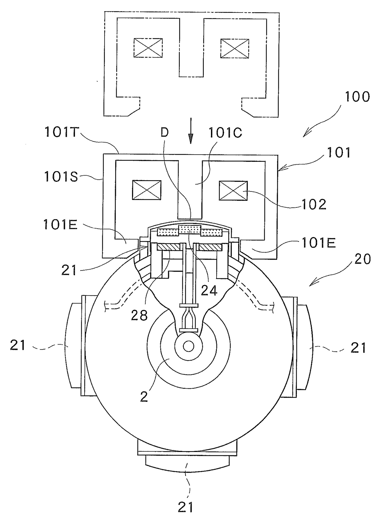
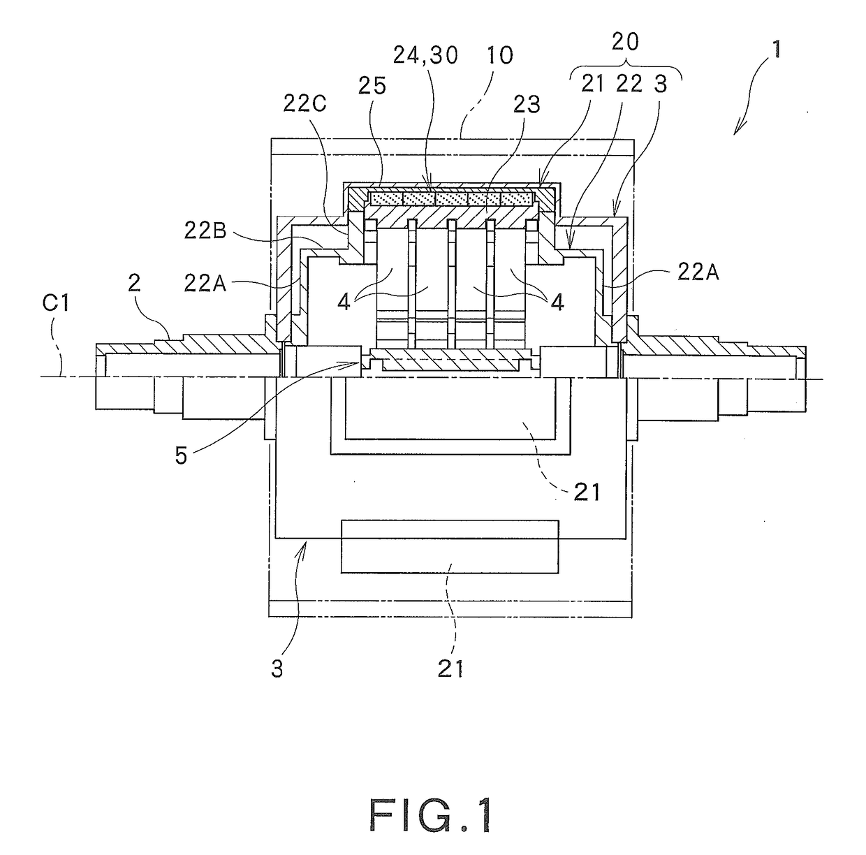
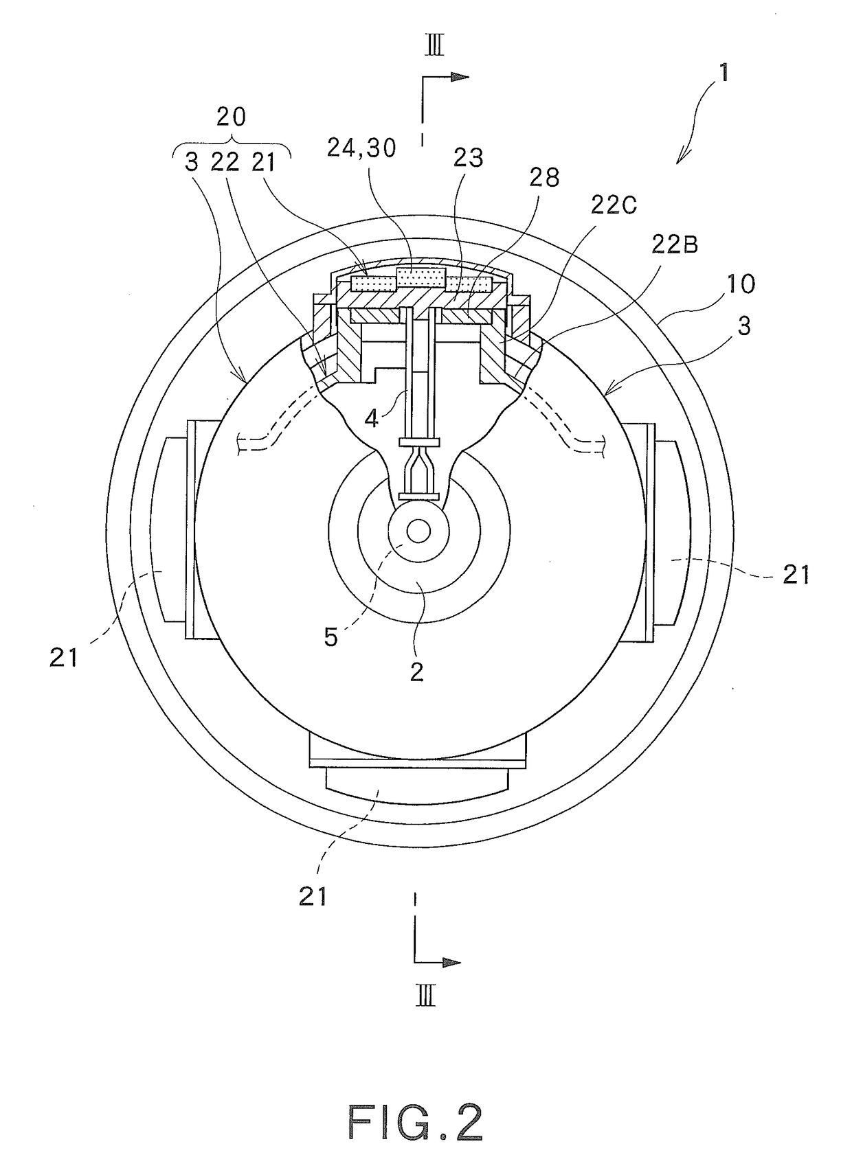
[0026]According to the radial-gap type superconducting synchronous machine of the present invention, when the superconductor disposed on the peripheral side of the rotor is magnetized by a magnetizing apparatus from outside in the radial direction of the rotor, a lot of magnetic flux lines from the magnetizing apparatus pass through the superconductor and are guided to the ferromagnet disposed on the rotational axis side of the superconductor. This enables concentrated magnetic flux lines to pass through the superconductor. Accordingly, the superconductor can be magnetized with high efficiency even when, for example, the coil of the magnetizing apparatus is disposed outside the superconductor in the radial direction of the rotor and at a distance from the superconductor, and the coil is not a large-sized one surrounding the superconductor. A sufficient captured magnetic flux can therefore be ensured in the superconductor even when magnetization is performed by a magnetizing apparatus which is not large-sized. Thus, captured magnetic flux in the superconductor can be effectively increased while ensuring the practical utility. This makes it possible to increase the torque and the power output of the synchronous machine.
[0027]In the radial-gap type superconducting synchronous machine of the present invention, when viewed in the direction of the rotational axis of the rotor, the magnetic pole center side of the superconductor is disposed nearer to the stator than the magnetic pole end side. Thus, the superconductor is disposed such that it follows the arc-shaped inner surface of the stator. This can reduce the gap between the superconductor and the stator, thereby making it possible to allow a magnetic field from the superconductor to efficiently act on the stator.
[0028]In the radial-gap type superconducting synchronous machine of the present invention, after the superconductor is magnetized by a magnetizing apparatus, the magnetized superconductor is attracted by the magnetic force to a magnetic portion of the magnetizing apparatus while, at the same time, the superconductor is attracted to the ferromagnet located on the rotational axis side of the superconductor. This can prevent the superconductor from moving toward the magnetizing apparatus, thus enabling the superconductor to be held in the initial installation position.
[0029]In the case where the superconductor is disposed in plural numbers at the distal end part of the magnetic pole, and the plurality of superconductors are disposed in such a stepped arrangement that when viewed in the direction of the rotational axis of the rotor, a superconductor closest to the center of the magnetic pole is located nearer to the stator than the other superconductors, the superconductor closest to the center of the magnetic pole can be easily disposed close to the stator.
[0030]In the case where the superconductor has a rectangular shape as viewed from outside in the radial direction of the rotor, the superconductor can efficiently capture magnetic flux lines, and the total amount of magnetic flux in the superconductor can be increased. This can increase the torque and the power output of the synchronous machine.
[0031]In the case where the superconductor is disposed in plural numbers at the distal end part of the magnetic pole, and the plurality of superconductors are disposed such that they are arranged in the circumferential direction of the rotor, and that they are arranged in the direction of the rotational axis of the rotor, a wide magnetic flux capturing area can be ensured with ease. This can increase the total amount of magnetic flux in magnetic flux capturing area, thereby increasing the torque and the power output of the synchronous machine.

Problems solved by technology

The axial-gap type superconducting synchronous machine of patent document 2, in performing its magnetization with the armature coil, uses pulse magnetization in order to prevent the magnetizing apparatus from becoming large-sized upon the integration of the magnetizing apparatus with the synchronous machine and thereby losing the practical utility.
Further, magnetization of the object is performed by applying the static magnetic field to the object for a long time.

Method used


Image

  • Radial-gap type superconducting synchronous machine, magnetizing apparatus and magnetizing method
  • Radial-gap type superconducting synchronous machine, magnetizing apparatus and magnetizing method
  • Radial-gap type superconducting synchronous machine, magnetizing apparatus and magnetizing method

Examples


examples

[0101]An example of the radial-gap type superconducting synchronous machine 1 will now be described. FIG. 13 is a diagram showing a table summarizing the performance of a radial-gap type superconducting synchronous machine of Example and the performances of conventional superconducting synchronous machines of Comp. Examples 1 to 3.

[0102]The table of FIG. 13 shows data on the “model” of each of the synchronous machines of Example and Comp. Examples 1 to 3, “rotational speed”, “torque” and “power output” as exemplary performance parameters, “superconducting material” used for a field system or an armature, “refrigerant or cooling method” for maintaining the superconducting material at a low temperature, and “captured magnetic flux density” in a magnetic pole.

[0103]The radial-gap type superconducting synchronous machine 1 of Example was magnetized by the magnetizing apparatus 100 in the manner described above with reference to the above embodiment, whereby magnetic flux lines were capt...


PUM

PropertyMeasurementUnit
temperatureaaaaaaaaaa
magnetic flux densityaaaaaaaaaa

Abstract

A radial-gap type superconducting synchronous machine 1 is prepared which includes a rotor 20 having, on its peripheral side, a convex magnetic pole 21 which includes, at its distal end part, bulk superconductors 30. When viewed in the direction of the rotational axis C1 of the rotor 20, the magnetic pole center side of the bulk superconductors 30 is disposed nearer to a stator 10 than the magnetic pole end side of the bulk superconductors 30. A ferromagnet 28 is disposed on the rotational axis C1 side of the bulk superconductors 30. A magnetizing apparatus 100 is disposed outside the bulk superconductors 30 in the radial direction of the rotor 20. Magnetization of the bulk superconductors 30 is performed by directing magnetic flux lines from the magnetizing apparatus 100 toward the bulk superconductors 30.

Description

TECHNICAL FIELD[0001]The present invention relates to a radial-gap type superconducting synchronous machine, a magnetizing apparatus and a magnetizing method, and more particularly to a technique for effectively increasing captured magnetic flux in an object to be magnetized while ensuring the practical utility.BACKGROUND ART[0002]Superconducting synchronous machines, which use a superconducting material for a field system or an armature, have attracted attention e.g. for the reason that a high power output can be obtained with high efficiency, and studies and proposals have been made thereon. As with common synchronous machines not using a superconducting material, superconducting synchronous machine can be classified broadly into a radial-gap type and an axial-gap type. Patent document 1 (Japanese Patent No. 5162654), for example, discloses a superconducting synchronous machine of the radial-gap type (hereinafter referred to as a radial-gap type superconducting synchronous machine...

Claims


Application Information

Patent Timeline
Patent Type & Authority Applications(United States)
IPC IPC(8): H02K21/14H01F6/00H01F13/00H02K15/03
CPCH02K21/14H01F6/00H01F13/003H02K15/03H02K55/04H02K1/02Y02E40/60H02K1/2796
Inventor IZUMI, MITSURUMIKI, MOTOHIRO
Owner TOKYO UNIV OF MANNE SCI & TECH
Why Eureka
Try Eureka