Apparatus and Method for Detecting Light Reflected From an Object

Inactive Publication Date: 2017-11-02
NOKIA TECHNOLOGLES OY
View PDF4 Cites 6 Cited by
  • Summary
  • Abstract
  • Description
  • Claims
  • Application Information

AI Technical Summary

Benefits of technology

[0011]According to at least some but not necessarily all examples of the disclosure the apparatus may be configured for use as a sensor for determining one or more of: a biometric measurem

Problems solved by technology

Conventional optical sensor s

Method used


Image

  • Apparatus and Method for Detecting Light Reflected From an Object
  • Apparatus and Method for Detecting Light Reflected From an Object
  • Apparatus and Method for Detecting Light Reflected From an Object

Examples


Embodiment Construction

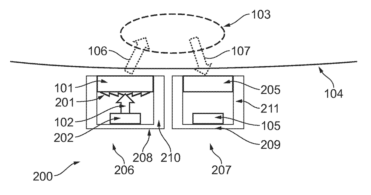
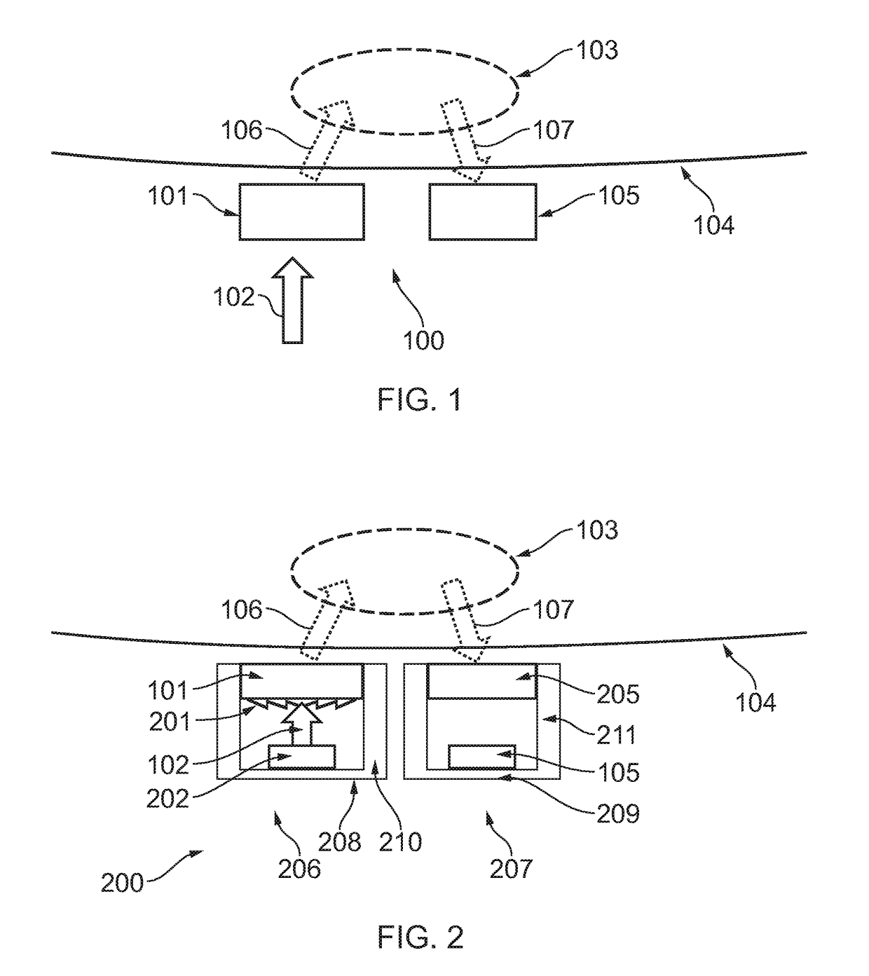
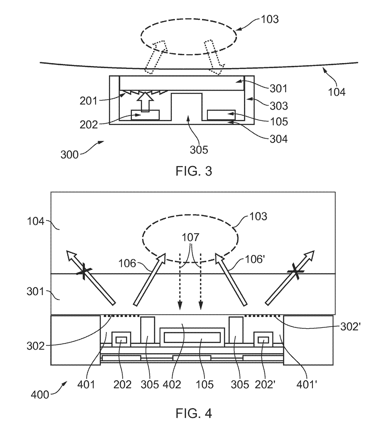
[0019]The Figures schematically illustrate an apparatus 100 comprising:[0020]a light guiding element 101 comprising a diffracting structure 302 configured to direct incident light 102 to an object 103; and[0021]an optical sensing element 105 configured to detect light reflected from said object 103.

[0022]The diffracting structure may, for example, be a diffractive optical element, a diffraction grating, a periodic structure / pattern or a series of diffraction lines / slits / grooves.

[0023]Certain examples of the present disclosure seek to provide an apparatus for re-orientating / focusing light to an object, such as a region of a user's body, so as to increase an amount of light that might be reflected from the object and detected by the optical sensing element. Increasing the amount of detected reflected light may improve the signal to noise ratio of the measurement of the reflected light. This may provide an advantage in that a lower brightness / luminous flux source of light might be empl...


PUM


Abstract

Examples of the present disclosure relate to an apparatus and method for detecting light reflected from an object. The apparatus includes a light guiding element including a diffracting structure configured to direct incident light to an object; and an optical sensing element configured to detect light reflected from said object.

Description

TECHNOLOGICAL FIELD[0001]Examples of the present disclosure relate to an apparatus and method for detecting light reflected from an object. Some examples, though without prejudice to the foregoing, relate to an apparatus and method for detecting light reflected from a user's body, e.g. skin, for determining biometric / physiological measurements, such as optically obtaining a volumetric measurement of an organ for a photoplethysmogram (PPG) to determine a user's heart rate.BACKGROUND[0002]Physiological / biometric measurements such as a user's heart rate may be measured from tissue using an optical PPG sensor. A change in volume caused by a pressure pulse from each cardiac cycle of a user's heart may be detected by a pulse oximeter which detects changes in light absorption within the skin of a user. The skin is illuminated, for instance from a light emitting diode (LED), and an amount of light reflected is measured, for instance with a photodetector.[0003]Conventional optical sensor sys...

Claims


Application Information

Patent Timeline
IPC IPC(8): A61B5/1455A61B5/026G01N21/47G01N21/49A61B5/0295
CPCA61B5/14552G01N21/474G01N21/49A61B5/0261A61B2562/0238G01N2201/0221G01N2201/08G01N2201/068A61B5/0295A61B5/02427G01N2021/178
Inventor LASAROV, HARRI
Owner NOKIA TECHNOLOGLES OY
Why Eureka
Try Eureka