Foam material generator

a foam generator and foam technology, applied in the direction of mixing, transportation and packaging, rotary stirring mixers, etc., can solve the problems of material production equipment the size, distribution uniformity, quantity and volume fraction of bubbles cannot be controlled, so as to achieve the effect of high strength, material resources can become very sufficient, and material resource problems can be solved thoroughly

Inactive Publication Date: 2017-11-02
CHEN JIUBIN
View PDF3 Cites 4 Cited by
  • Summary
  • Abstract
  • Description
  • Claims
  • Application Information

AI Technical Summary

Benefits of technology

[0015]The present invention has the following advantages: a new structure and a new mixing and foaming method are adopted; a gas is separated into tiny bubbles through the mixing and stretching actions of a moving eddy current on a fluid; the melt and the bubbles are fully and uniformly mixed to form foams; the foams are cooled and solidified to form a foam material with uniform and fine bubbles and uniform bubble arrangement; the foam material generator, serving as material production equipment, can produce a new foam material with higher strength; the material can be widely used for material industry, mechanical industry and construction industry, etc.; the foam material generator can produce a new nano-foam material; the material is a real nano-material with the advantages both nano-material and foam material and many magic material performances; a great number of low-cost, energy-saving, environment-friendly and high-quality materials can be obtained, the material resources can become very sufficient, and the material resource problem can be solved thoroughly; material nanocrystallization extremely improves material performance, and material bubbling extremely reduces resource utilization amount; the foam material is a composite material combining soft and hard materials, and can extremely expand material application scope and space.

Problems solved by technology

The existing foam material production equipment has many problems, such as foam materials with uniform bubbles can not be produced, and the size, distribution uniformity, quantity and volume fraction of bubbles can not be controlled.
Especially, as the production technology of foam metal and foam glass is primitive and backward, high performance foam materials are not used as they are supposed to be, and are not produced at low cost or applied extensively.
The existing technology can not produce more excellent materials such as nano-foam materials and foam metal glass.
During the existing production of nano-materials, nano-particles are damaged, and the material performance is largely degraded.
The existing material production generally lacks a key process of material production, that is, material bubbling.

Method used


Image

  • Foam material generator
  • Foam material generator
  • Foam material generator

Examples


first embodiment

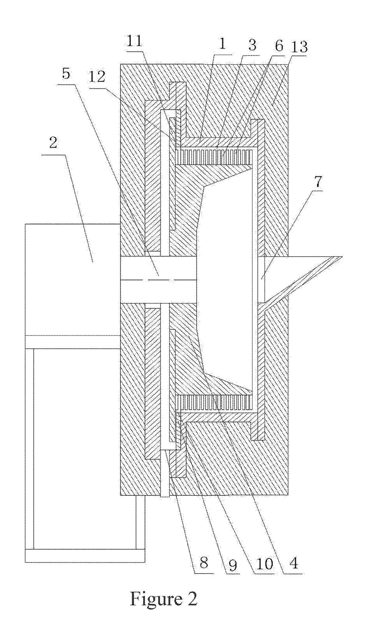
[0032]The structure of the present invention is as follows: based on the major structure, a thermal insulation device 13 is disposed on the outer wall of the housing cavity 3; the thermal insulation device 13 can cover the outer wall of the housing cavity 3; the thermal insulation device 13 can be made of a heat-resisting thermal insulation material; a protective covering can be disposed on the outermost layer of the thermal insulation device 13; the protective covering can also be used as a safety protection covering; it can simply be filled with a thermal insulation mineral wool; the thermal insulation material layer can also be utilized to improve the leak tightness between the transmission shaft and the housing; the thermal insulation device 13 can prevent heat loss, so as to better ensure that the foam material generator runs properly; a heating unit can also be disposed inside the thermal insulation device 13 for better thermal insulation and heating, so as to better ensure th...

second embodiment

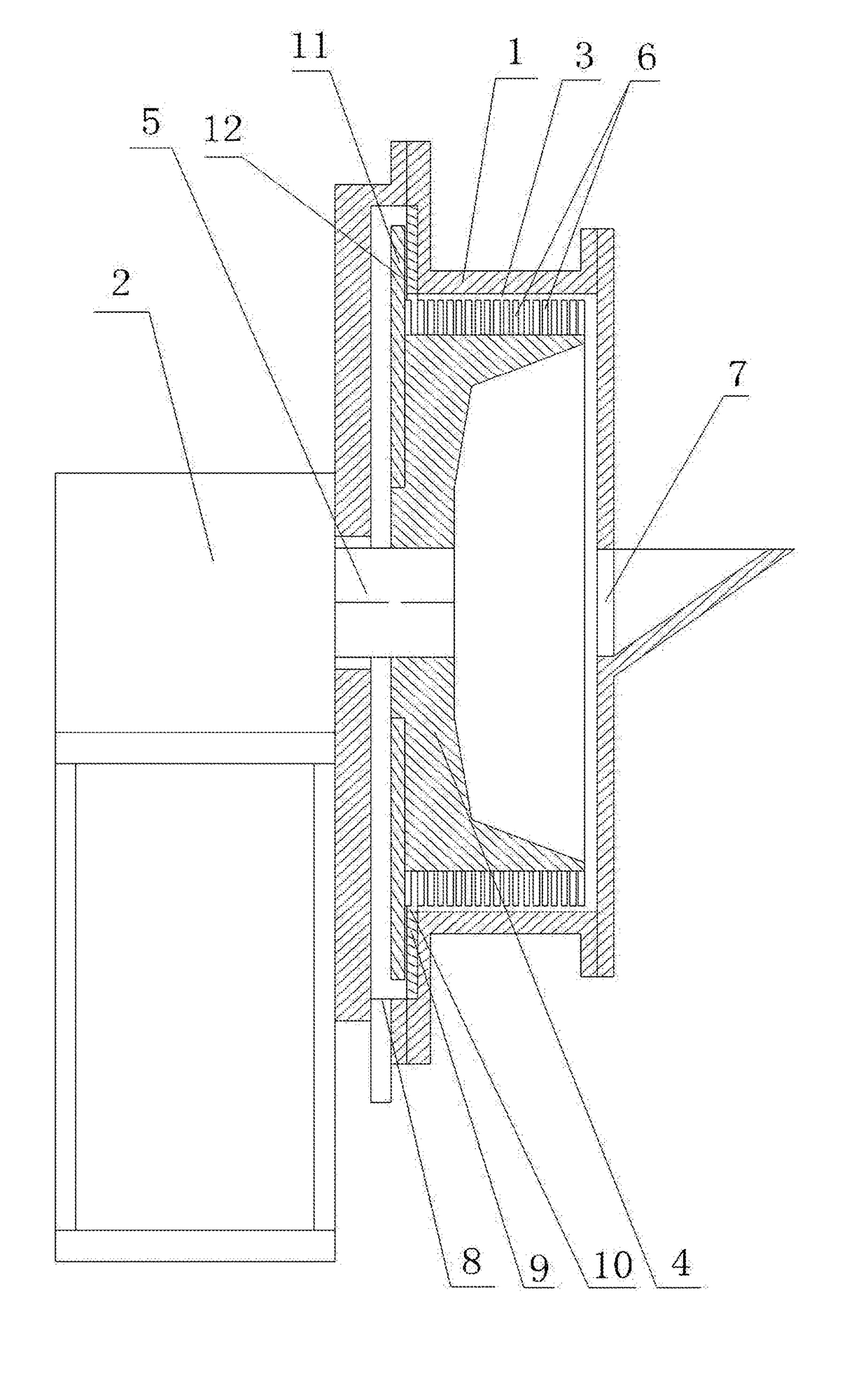
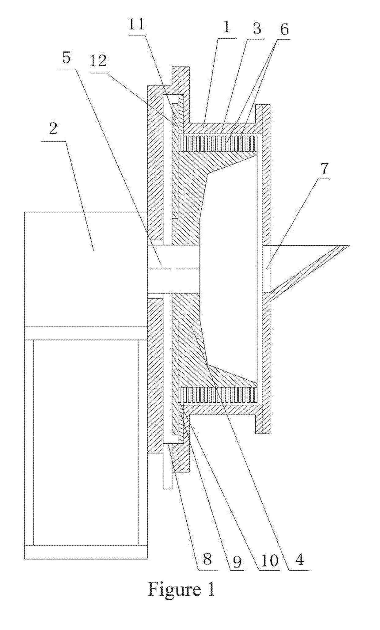
[0034]The structure of the present invention is as follows: based on the foregoing structure, the bottom inner wall of the housing cavity 3 is gradually elevated towards the housing cavity outlet 8; when the foam material generator is installed, the transmission shaft 5 can be obliquely placed, so that the bottom inner wall of the housing cavity 3 can be gradually elevated towards the housing cavity outlet 8, and the melt can be gathered in the housing cavity inlet 7; thus, the foams with better foaming effect and smaller specific gravity axially move towards the housing cavity outlet 8 under the action of the supercharged stirring foaming wheel 4, and the melt with poorer foaming effect and larger specific gravity returns back to the housing cavity inlet 7 along the bottom of the housing cavity 3 for continuous foaming.

[0035]The foam material generator of this embodiment has all functions of the foregoing structure, and can improve the foaming effect.

third embodiment

[0036]The structure of the present invention is as follows: based on the foregoing structure, a transmission device position regulating device 14 is disposed between the housing 1 and the transmission device 2; the transmission device position regulating device 14 can be disposed between the housing 1 and the transmission device 2; the transmission device position regulating device 14 can be provided with a screw and a nut, etc.; the transmission device position regulating device 14 can be disposed on a mounting stand of the housing 1; the position of the transmission device 2 can be regulated by regulating the screw and the nut; the nut can be fixed on the mounting stand of the housing 1, while the screw can be regulated; two groups of regulating screws and nuts can be disposed for two-way regulation, so as to regulate the position of the transmission device 2 back and forth; the transmission device position regulating device 14 can regulate the position of the supercharged stirrin...


PUM

PropertyMeasurementUnit
specific gravityaaaaaaaaaa
thickaaaaaaaaaa
thickaaaaaaaaaa

Abstract

A foam material generator has a housing; transmission device on the housing; housing cavity within the housing; pressurizing stirring foaming wheel within the cavity; transmission device transmission shaft connected to the wheel; pressurizing stirrers on the wheel; pressurizing stirrer airflow-facing surface forms an inclined angle with a cross sectional surface in a wheel rotational axis direction; housing cavity inlet is on a cavity end, and a housing cavity outlet is on another end; encircling abrasive disc is on a cavity inner wall adjacent to the outlet; encircling abrasive disc inlet is at a encircling disc middle portion; vortex current abrasive foaming disc is on a wheel end adjacent to the encircling disc; vortex current abrasive foaming disc surface conforms to be in close proximity with an encircling disc surface; and vortex current abrasive foaming cavity is between the surfaces of the vortex current abrasive foam disc and encircling disc.

Description

TECHNICAL FIELD[0001]The present invention relates to the field of material production equipment, and specifically to a foam material generator, which can be used as foam material production equipment to produce a new foam material or new nano-foam material.BACKGROUND ART[0002]The existing foam material production equipment has many problems, such as foam materials with uniform bubbles can not be produced, and the size, distribution uniformity, quantity and volume fraction of bubbles can not be controlled. Especially, as the production technology of foam metal and foam glass is primitive and backward, high performance foam materials are not used as they are supposed to be, and are not produced at low cost or applied extensively. The existing technology can not produce more excellent materials such as nano-foam materials and foam metal glass. During the existing production of nano-materials, nano-particles are damaged, and the material performance is largely degraded. The existing ma...

Claims


Application Information

Patent Timeline
Patent Type & Authority Applications(United States)
IPC IPC(8): B01F3/04B01F7/00B01F7/10B01F15/00B01F15/06B01F27/73
CPCB01F3/04453B01F7/008B01F2015/061B01F15/00331B01F7/10B01F15/066B01F23/2351B01F27/2711B01F27/2722B01F2035/98B01F35/93B01F27/73B01F27/272B01F35/221
Inventor CHEN, JIUBIN
Owner CHEN JIUBIN
Why Eureka
Try Eureka