Composite material with insert-molded attachment steel

a technology of composite materials and attachment steels, which is applied in the direction of transportation and packaging, vehicle sub-unit features, and other domestic articles, etc., can solve the problems of combining different materials related to welding properties or corrosion, not producing the desired rigidity, and not being suitable for mass production, so as to achieve the effect of improving shear strength between the composite material and the attachment steel and increasing the thickness of the fibers

Active Publication Date: 2017-11-02
HYUNDAI MOTOR CO LTD
View PDF7 Cites 1 Cited by
  • Summary
  • Abstract
  • Description
  • Claims
  • Application Information

AI Technical Summary

Benefits of technology

[0006]The present invention provides a composite material with an insert-molded attachment steel to improve shear strength between the composite material and the attachment steel by forming the attachment steel. The attachment steel may include a flange disposed between fibers by insert-molding and introduces a resin.
[0009]According to the exemplary embodiment of the present invention, the shear strength reinforcing portion may be formed by introducing resin between the fibers. The attachment steel may have a flange in one direction formed by insert-molding between the fibers and thus, the thicknesses of the fibers may be increased, and as a result the shear strength between the composite material and the attachment steel may be improved. Additionally, other effects obtained or expected by the exemplary embodiments of the present invention will be directly or implicitly disclosed in the detailed description of the exemplary embodiments of the present invention. That is, various effects expected according to the exemplary embodiments of the present invention will be disclosed in the detailed description to be described below.

Problems solved by technology

In particular, there are disadvantages to combining the different materials related to welding properties or corrosiveness.
Accordingly, methods of mechanical attachment are largely used, however this has not produced the desired rigidity.
The composite material is fastened to the steel material by bolting through the aperture and as a result, the structure is not appropriate for mass production since assembly process is slow.
However, the insertion of the connecting member causes the occurrence of cracks since the connecting member is not properly or securely attached to the composite material.

Method used


Image

  • Composite material with insert-molded attachment steel
  • Composite material with insert-molded attachment steel
  • Composite material with insert-molded attachment steel

Examples


Embodiment Construction

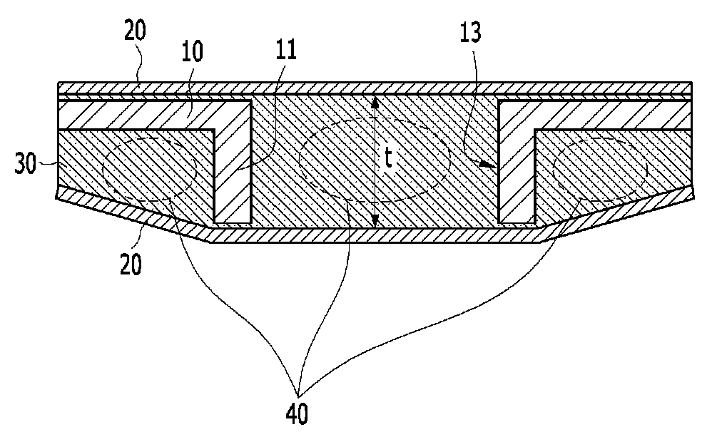
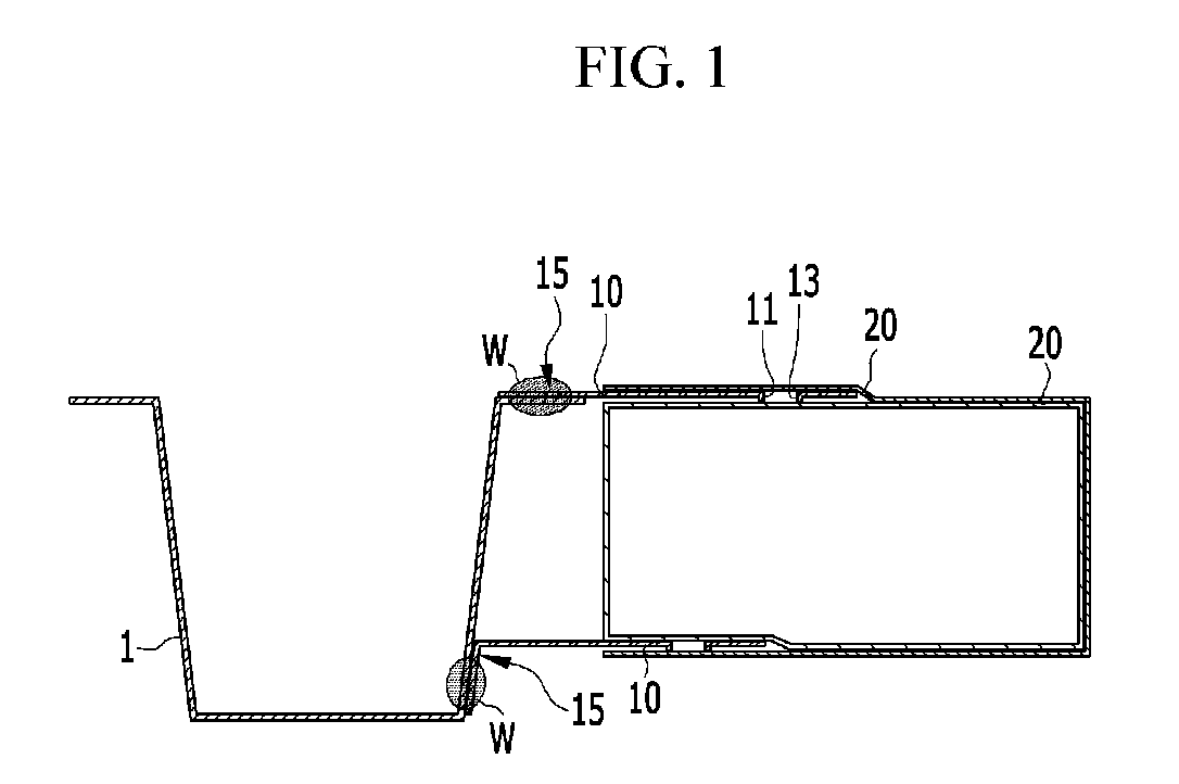
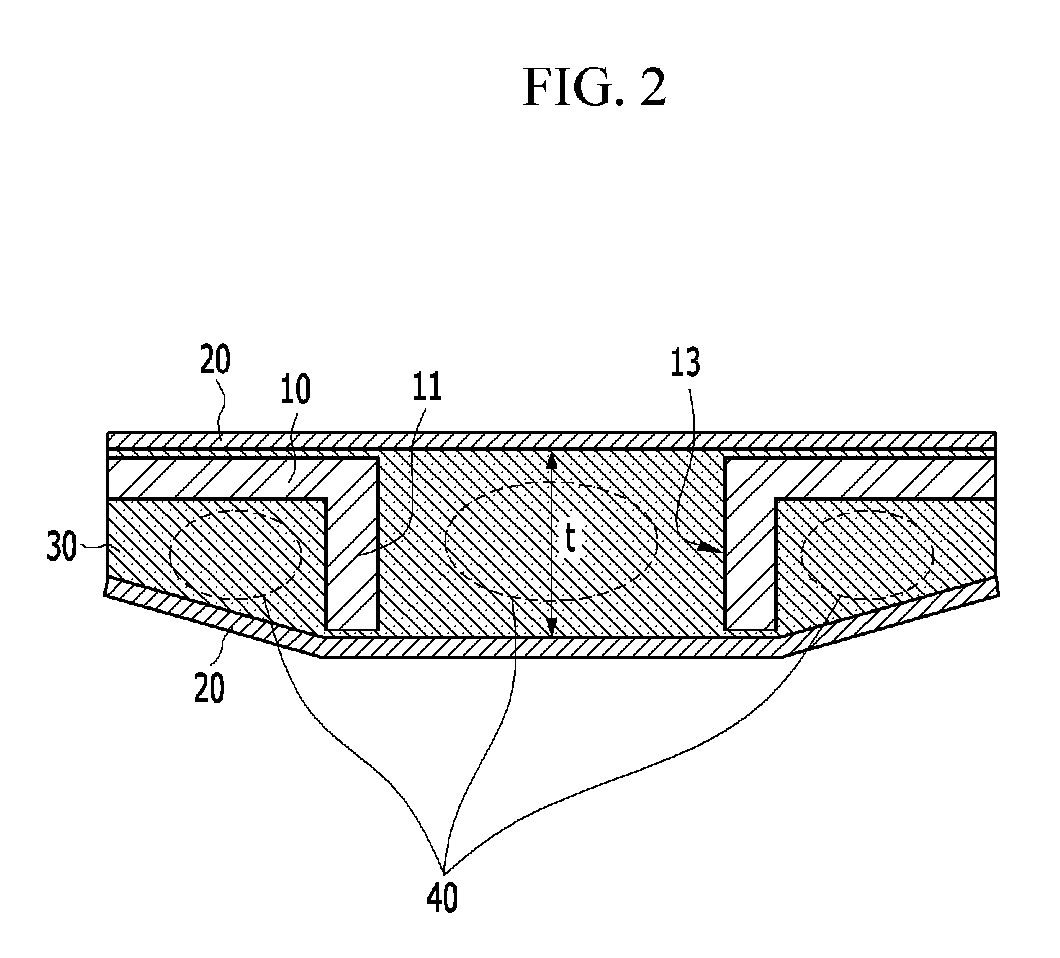
[0021]Hereinafter, an exemplary embodiment of the present invention will be described with reference to the accompanying drawings. However, the drawings illustrated below and the following description relate to one exemplary embodiment among various exemplary embodiments for effectively explaining features of the present invention. While the invention will be described in conjunction with exemplary embodiments, it will be understood that present description is not intended to limit the invention to those exemplary embodiments. On the contrary, the invention is intended to cover not only the exemplary embodiments, but also various alternatives, modifications, equivalents and other exemplary embodiments, which may be included within the spirit and scope of the invention as defined by the appended claims.

[0022]The terminology used herein is for the purpose of describing particular exemplary embodiments only and is not intended to be limiting of the invention. As used herein, the singul...


PUM

PropertyMeasurementUnit
shear strengthaaaaaaaaaa
thicknessaaaaaaaaaa
heightaaaaaaaaaa

Abstract

A composite material with an insert-molded attachment steel is provided. The composite material includes a plurality of burring apertures, each of which has a flange in one direction on the attachment steel and is inserted between fibers. A resin is then introduced between the fibers in each burring aperture and external to the flange.

Description

CROSS-REFERENCE TO RELATED APPLICATION[0001]This application claims priority to and the benefit of Korean Patent Application No. 10-2016-0052105 filed in the Korean Intellectual Property Office on Apr. 28, 2016, the entire contents of which are incorporated herein by reference.BACKGROUNDField of the Invention[0002]The present invention relates to a composite material with an insert-molded attachment steel, and more particularly, to a insert-molded attachment steel that reinforces the shear strength between the composite material and the attachment steel.Description of the Related Art[0003]Generally, development of a vehicle requires that the vehicle have a high-strength while also being lightweight. Accordingly, a vehicle body formed from a material such as aluminum or a composite material that is light in weight, has excellent rigidity and a high degree of design freedom compared with a steel material. Since new materials such as aluminum or the composite material are used for the ...

Claims


Application Information

Patent Timeline
Patent Type & Authority Applications(United States)
IPC IPC(8): B32B15/14B32B5/02B29C65/00B29C65/70B62D29/00B32B3/26B29K105/06B29K705/00B29L31/30
CPCB32B15/14B32B5/02B32B3/266B29C65/70B29C66/742B62D29/004B29L2031/30B32B2260/046B32B2307/542B32B2605/00B29K2705/00B29K2105/06B32B2260/023B32B3/26B32B15/08B32B15/18B32B27/12B32B2262/0269B32B2262/101B32B2262/106B32B5/26B32B7/08B32B15/043B32B27/08B32B2605/08Y10T428/24174Y10T428/24182Y10T428/2419Y10T428/24289Y10T428/24331Y10T428/24339Y10T428/24347B29C65/002B29C65/72B29C70/68B29C65/54B29C66/02242B29C66/12221B29C66/303B29C66/304B29C66/346B29C66/72B29C66/7212B29C66/74283B29C70/72B29C70/745B29C70/845B29K2101/00B29K2705/12B29L2031/3002B29L2031/3055B32B3/06B32B3/28B32B3/30B32B5/24B32B7/12B32B2262/105B32B2305/073B32B2305/34B32B2311/30B32B2398/00B60Y2410/123B60Y2410/124B60Y2410/125B62D29/005
Inventor SONG, WON KI
Owner HYUNDAI MOTOR CO LTD
Why Eureka
Try Eureka