Camera Module Including Liquid Lens, Optical Device Including the Same, and Method of Manufacturing Camera Module Including Liquid Lens

a technology of liquid lens and camera module, which is applied in the field of camera modules, can solve the problems of high power consumption of the lens moving apparatus, and achieve the effects of reducing the time, effort and cost required to manufacture and simplifying the structure of the lens and the camera module including the sam

Active Publication Date: 2017-11-02
LG INNOTEK CO LTD
View PDF2 Cites 50 Cited by
  • Summary
  • Abstract
  • Description
  • Claims
  • Application Information

AI Technical Summary

Benefits of technology

[0071]In embodiments, the deposition layer formed on the upper surface and the lower surface of the core may be connected to an external power supply via the pattern unit formed on the lower surface of the core. Consequently, the lens may have a structure that is simpler than the structure in which the deposition layer formed on the upper surface and the lower surface of the core is connected to the external power supply.
[0072]In addition, since the lens has a simple structure, the structure of the lens and the camera module including the same may be simplified and miniaturized. As a result, the time, effort, and cost required to manufacture the lens and the camera module including the same may be reduced.
[0073]In addition, the use of an additional cover glass to protect the exposed portion of t...

Problems solved by technology

However, the lens moving apparatus has high power consumption, driving members, such as a magnet and a coil, are required to move the len...

Method used


Image

  • Camera Module Including Liquid Lens, Optical Device Including the Same, and Method of Manufacturing Camera Module Including Liquid Lens
  • Camera Module Including Liquid Lens, Optical Device Including the Same, and Method of Manufacturing Camera Module Including Liquid Lens
  • Camera Module Including Liquid Lens, Optical Device Including the Same, and Method of Manufacturing Camera Module Including Liquid Lens

Examples


first embodiment

[0240]Hereinafter, the structure of a camera module 2000 will be described with reference to the drawings.

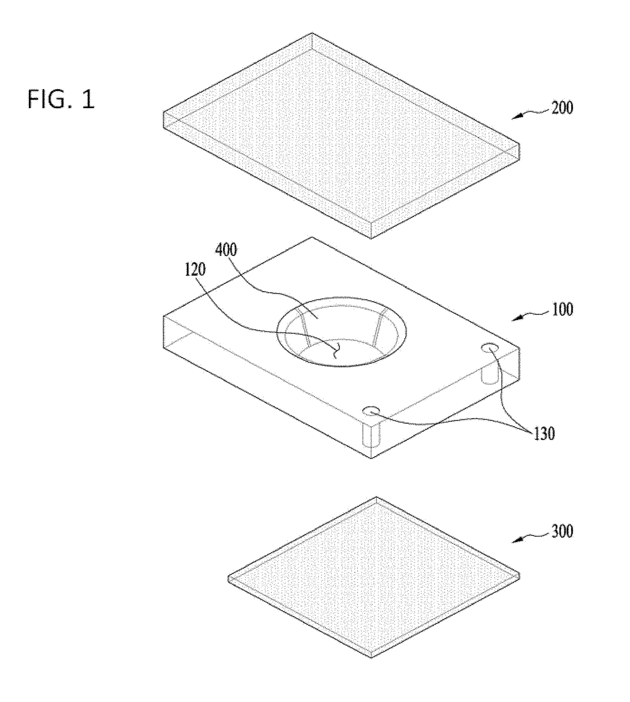
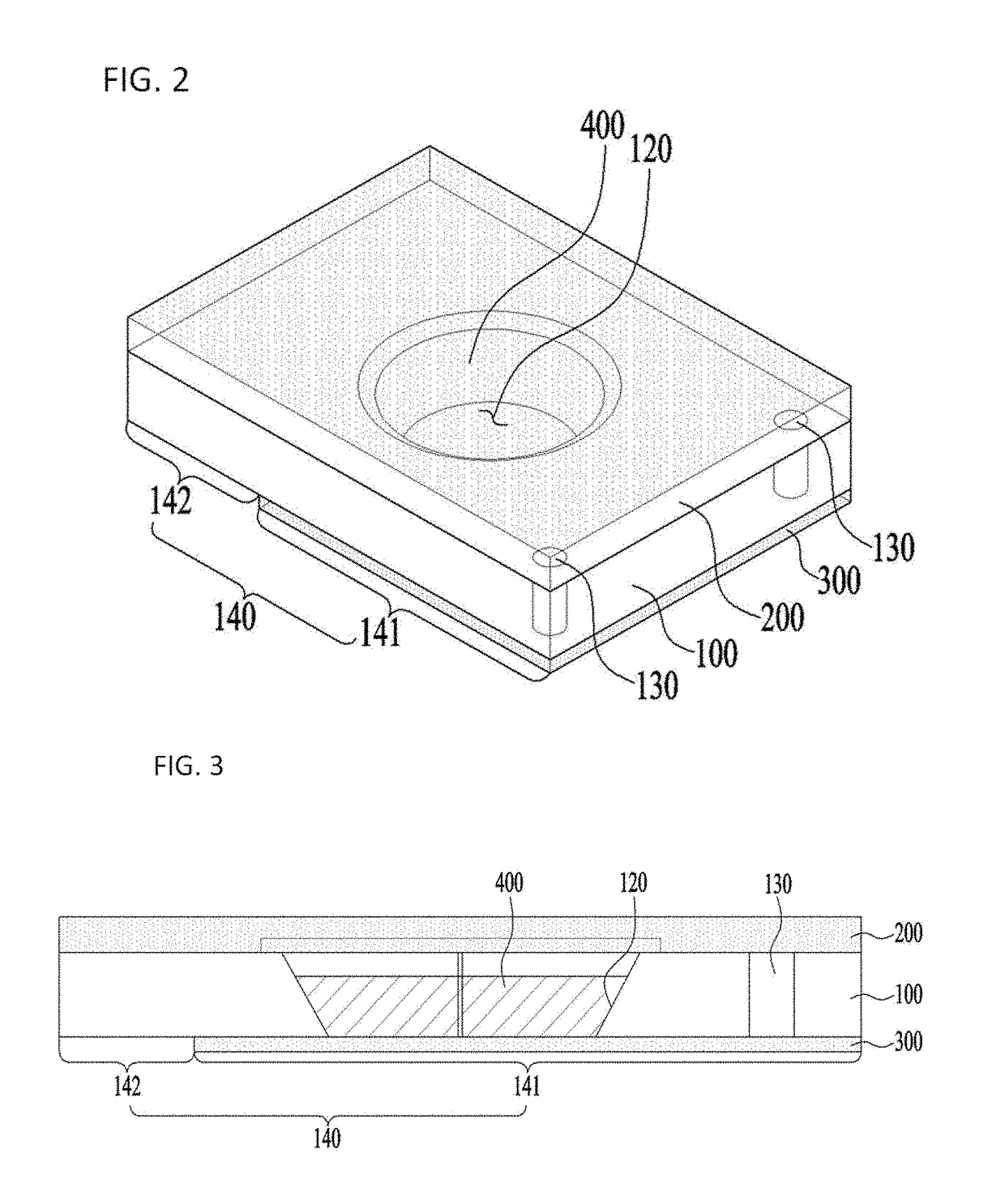
[0241]FIG. 16 is a perspective view showing a camera module according to first and second embodiments, FIG. 17 is an exploded perspective view showing the camera module according to the first embodiment, FIG. 18 is a perspective view showing a shield can according to a first embodiment, FIG. 19 is a perspective view showing a lens holder according to a first embodiment, FIG. 20 is a sectional view showing the lens holder according to the first embodiment, FIG. 21 is an exploded perspective view showing a liquid lens according to a first embodiment, FIG. 22 is a plan view showing the liquid lens according to the first embodiment, FIGS. 23A to 23L are conceptual sectional views showing that a conductive liquid and a nonconductive liquid are received in a cavity in first and second embodiments, and FIG. 24 is a sectional view showing the camera module according to the first embodi...

second embodiment

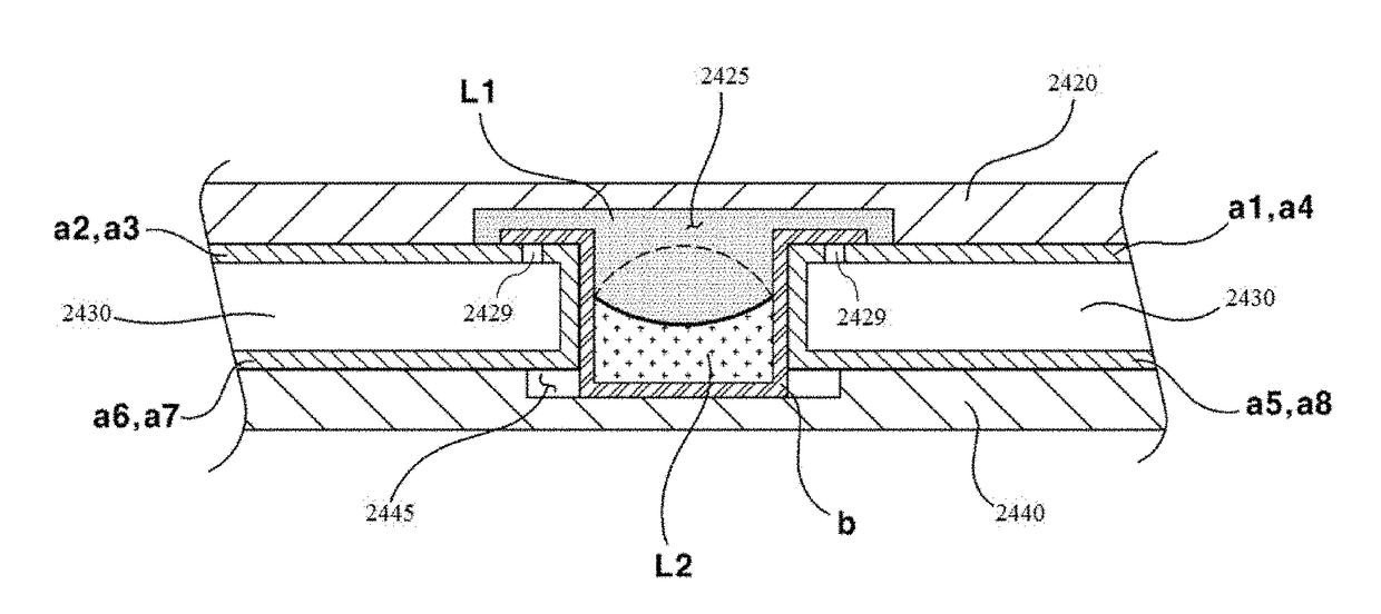
[0336]In a modification (not shown), the nonconductive liquid may be located in the upper portion of the cavity, and the conductive liquid may be located in the lower portion of the cavity. In this case, the insulation layer may be located in a reverse state. That is, a circular insulation layer may be coated on a portion of the upper recess, and a circular insulation layer may be coated on the lower surface of the core plate along the circumference of the cavity. In addition, no circular insulation layer may be coated on a portion of the lower recess, and no circular insulation layer may be coated on the upper surface of the core plate along the circumference of the cavity. In this structure, the operation of the first or second embodiment is reversely carried out to perform the AF and OIS functions.

[0337]Hereinafter, a method of manufacturing the lens module according to the first or second embodiment will be described with reference to the drawings. FIG. 28 is a conceptual view s...


PUM


Abstract

An embodiment of a camera module includes a holder configured such that the upper and lower portions of the holder are open and such that a first hole and a second hole, opposite to the first hole, are formed in the side surface of the holder, a first lens unit coupled to the upper portion of the holder, a second lens unit coupled to the lower portion of the holder, and a liquid lens disposed in the first hole and the second hole of the holder between the first lens unit and the second lens unit, the liquid lens protruding outward from the side surface of the holder, wherein at least a portion of the liquid lens may be spaced apart from the inner surface of the holder.

Description

CROSS-REFERENCE TO RELATED APPLICATIONS[0001]This application is a continuation of International Patent Application No. PCT / KR2017 / 004615, filed Apr. 28, 2017, which claims priority to Korean Application Nos. 10-2016-0052778, filed Apr. 29, 2016; 10-2016-0056227, filed May 9, 2016; 10-2016-0114133, filed Sep. 5, 2016; and 10-2017-0013046, filed Jan. 26, 2017, the disclosures of each of which are incorporated herein by reference in their entirety.TECHNICAL FIELD[0002]Embodiments relate to a camera module, and more particularly to a camera module including a liquid lens and an optical device including the same.BACKGROUND ART[0003]People who use portable devices demand optical devices that have high resolution, are small, and have various photographing functions (an auto-focusing (AF) function, a handshake compensation or optical image stabilization (OIS) function, etc.). Such photographing functions may be realized by directly moving a plurality of lenses that are combined. In the cas...

Claims


Application Information

Patent Timeline
IPC IPC(8): G02B3/14H04N5/232H04N5/225G02B26/00G03B13/36
CPCG02B3/14H04N5/2254H04N5/2253H04N5/23293G02B2207/121H04N5/23287G02B26/004G03B13/36H04N5/23216G02B7/02G02B6/12G02B7/08G02B13/0075G02B27/646G03B29/00G03B2217/002H04N23/54H04N23/55H04N23/63G02B3/00G02B3/12H04N23/62H04N23/687
Inventor PARK, SEUNG RYONGBAIK, JUNG SHIK
Owner LG INNOTEK CO LTD
Why Eureka
Try Eureka