Lighting device with ceramic garnet

a lighting device and ceramic garnet technology, applied in the field of lighting devices, can solve the problems of reducing the efficiency of light generation inside the rod, prone to saturation of ceramic garnet compositions, and affecting the efficiency of lighting devices using high excitation fluxes, and achieves a substantial reduction in the efficiency of lighting devices using ceramics than when using single crystals

Active Publication Date: 2017-11-02
KONINKLJIJKE PHILIPS NV
View PDF2 Cites 26 Cited by
  • Summary
  • Abstract
  • Description
  • Claims
  • Application Information

AI Technical Summary

Benefits of technology

[0044]In an embodiment, the light source may also provide light source light having a correlated color temperature (CCT) between about 5000 and 20000 K, e.g. direct phosphor converted LEDs (blue light emitting diode with thin layer of phosphor for e.g. obtaining of 10000 K). Hence, in a specific embodiment the light sou

Problems solved by technology

However, it was surprisingly found that ceramic garnet compositions are prone to saturation, i.e. the efficiency of light generation inside the rod is reduced when the light intensity (of the pump light) increases.
Further, it was surprisingly found that single crystals under (almost) the same conditions do not show this effect, or to a

Method used


Image

  • Lighting device with ceramic garnet
  • Lighting device with ceramic garnet
  • Lighting device with ceramic garnet

Examples


Embodiment Construction

[0056]A light emitting device according to the invention may be used in applications including but not being limited to a lamp, a light module, a luminaire, a spot light, a flash light, a projector, a (digital) projection device, automotive lighting such as e.g. a headlight or a taillight of a motor vehicle, arena lighting, theater lighting and architectural lighting.

[0057]Light sources which are part of the embodiments according to the invention as set forth below, may be adapted for, in operation, emitting light with a first spectral distribution. This light is subsequently coupled into a light guide or waveguide; here the ceramic body. The light guide or waveguide may convert the light of the first spectral distribution to another spectral distribution and guides the light to an exit surface.

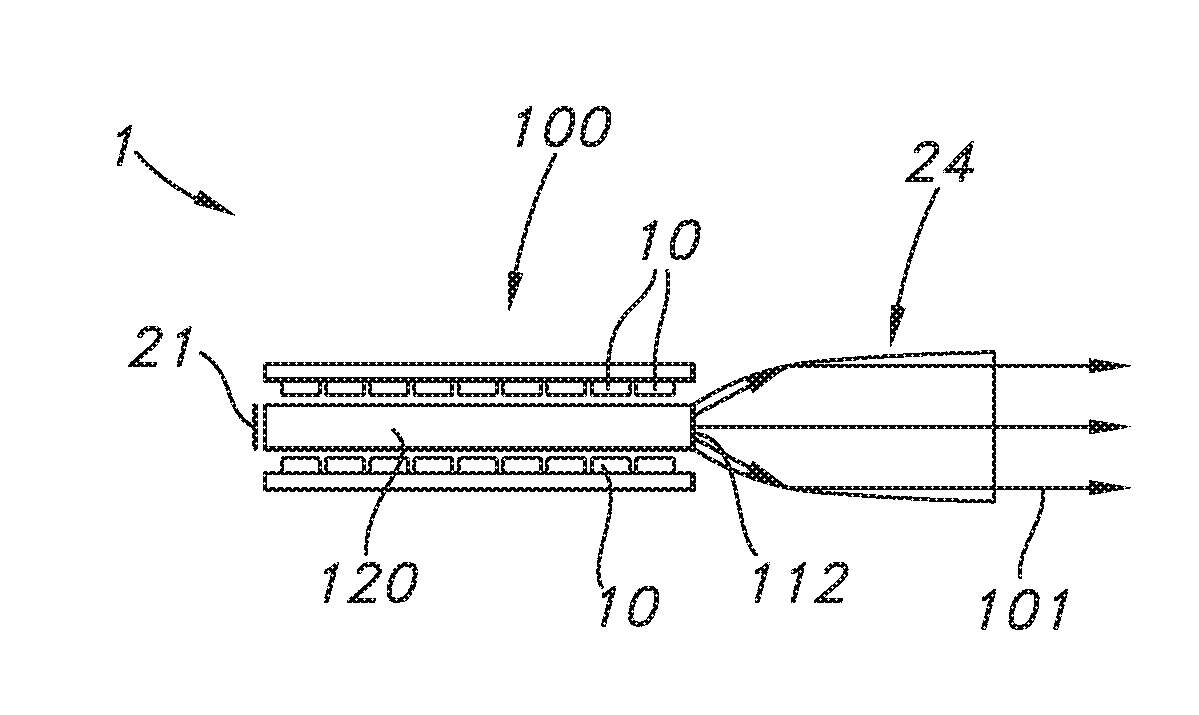
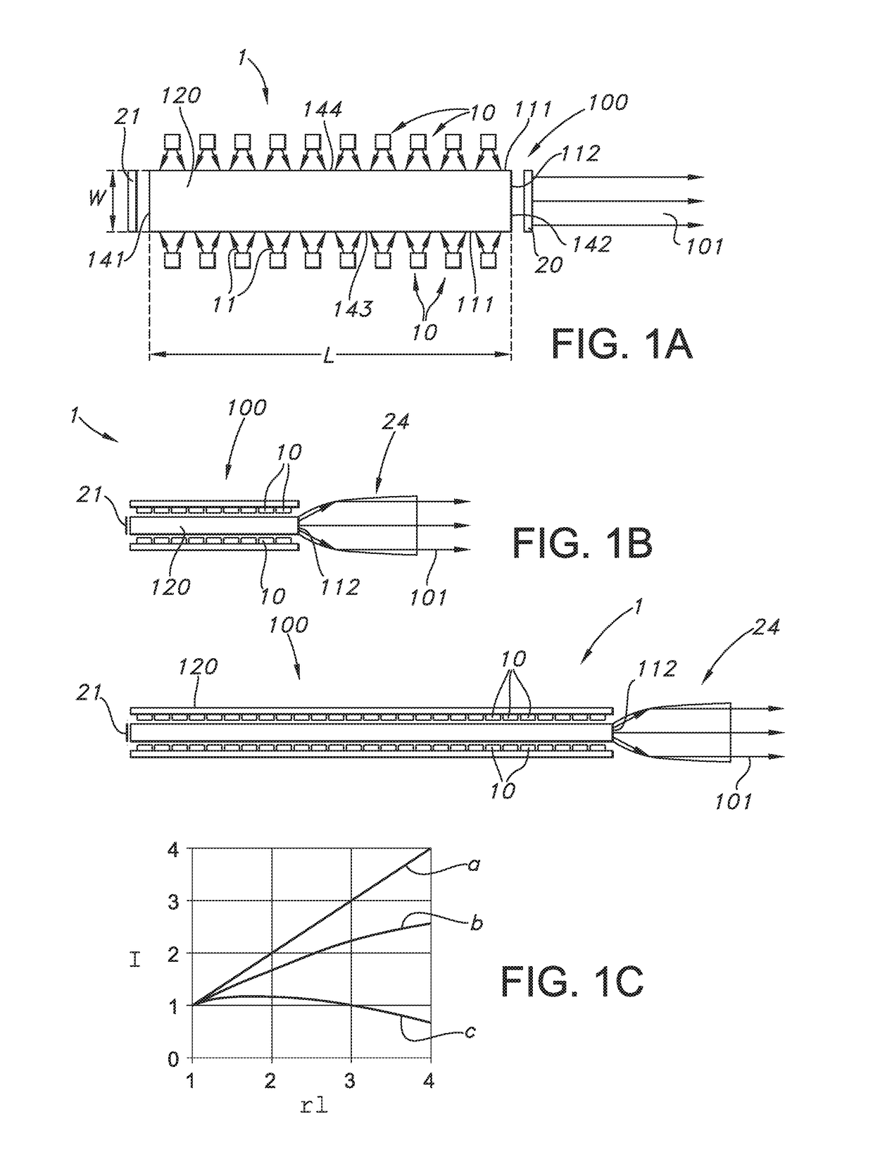
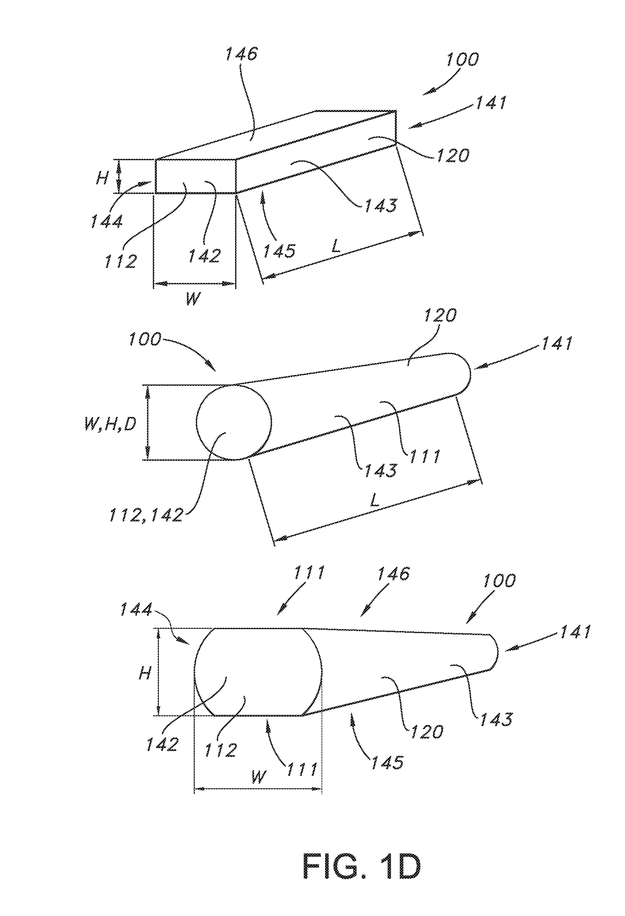
[0058]An embodiment of the lighting device as defined herein is schematically depicted in FIG. 1a. FIG. 1a schematically depicts a lighting device 1 comprising a plurality of solid state ligh...


PUM

PropertyMeasurementUnit
Temperatureaaaaaaaaaa

Abstract

The invention provides a lighting device comprising a plurality of solid state light sources and an elongated ceramic body having a first face and a second face defining a length (L) of the elongated ceramic body, the elongated ceramic body comprising one or more radiation input faces and a radiation exit window, wherein the second face comprises the radiation exit window, wherein the plurality of solid state light sources are configured to provide blue light source light to the one or more radiation input faces and are configured to provide to at least one of the radiation input faces a photon flux of at least 1.0*1017 photons/(s·mm2), wherein the elongated ceramic body comprises a ceramic material configured to wavelength convert at least part of the blue light source light into at least converter light, wherein the ceramic material comprises an A3B5O12:Ce3+ ceramic material, wherein A comprises one or more of yttrium (Y), gadolinium (Gd) and lutetium (Lu), and wherein B comprises aluminum (Al).

Description

FIELD OF THE INVENTION[0001]The invention relates to a lighting device, such as for use in a projector. The invention further relates to a ceramic garnet for used in such lighting device, as well as a method for the production of such ceramic garnet.BACKGROUND OF THE INVENTION[0002]Luminescent rods are known in the art. WO2006 / 054203, for instance, describes a light emitting device comprising at least one LED which emits light in the wavelength range of >220 nm to <550 nm and at least one conversion structure placed towards the at least one LED without optical contact, which converts at least partly the light from the at least one LED to light in the wavelength range of >300 nm to ≦1000 nm, characterized in that the at least one conversion structure has a refractive index n of >1.5 and <3 and the ratio A:E is >2:1 and <50000:1, where A and E are defined as follows: the at least one conversion structure comprises at least one entrance surface, where light emitted...

Claims


Application Information

Patent Timeline
IPC IPC(8): G03B21/20C04B35/44F21V8/00C09K11/77F21V9/08C04B35/64G02B27/30F21V29/503F21V29/70G03B21/16
CPCG03B21/204C04B2235/656G03B21/2066G03B21/2013G02B27/30G02B6/0008G02B6/0006C09K11/7774C04B35/44C04B35/64F21Y2115/10F21Y2115/30F21V29/503F21V29/70G03B21/16C04B2235/3224C04B2235/3225C04B2235/3229C04B2235/3222C04B2235/604C04B2235/663F21V9/08C04B35/6455F21V7/22F21V9/00C04B2235/764C04B2235/95C04B2235/94C04B2235/664C04B2235/6584C04B2235/6581
Inventor RONDA, CORNELIS REINDERBOEREKAMP, JACOBUS GERARDUSJAGT, JOHANNES BOUDEWIJN
Owner KONINKLJIJKE PHILIPS NV
Why Eureka
Try Eureka