Supercharge Your Innovation With Domain-Expert AI Agents!

Depth detection apparatus, imaging apparatus and depth detection method

a technology of depth detection and depth measurement, applied in the field of depth detection apparatus, imaging apparatus and depth detection method, can solve the problems of depth measurement accuracy drop, fluctuation of conversion coefficient, etc., and achieve high speed and high precision

Active Publication Date: 2017-11-09
CANON KK
View PDF1 Cites 4 Cited by
  • Summary
  • Abstract
  • Description
  • Claims
  • Application Information

AI Technical Summary

Benefits of technology

The present invention provides a depth detection system and method that can quickly and accurately measure depth. This may be useful in various applications where depth detection is important.

Problems solved by technology

A cause of a drop in the depth measurement accuracy is the change of profile of an image signal generated by each photoelectric conversion unit.
Another cause of a drop in the depth measurement accuracy is fluctuation of the conversion coefficient.
If the shift amount is converted into the defocus amount using a fixed conversion coefficient regardless the depth measurement conditions, a conversion error occurs.

Method used


Image

  • Depth detection apparatus, imaging apparatus and depth detection method
  • Depth detection apparatus, imaging apparatus and depth detection method
  • Depth detection apparatus, imaging apparatus and depth detection method

Examples


embodiment 1

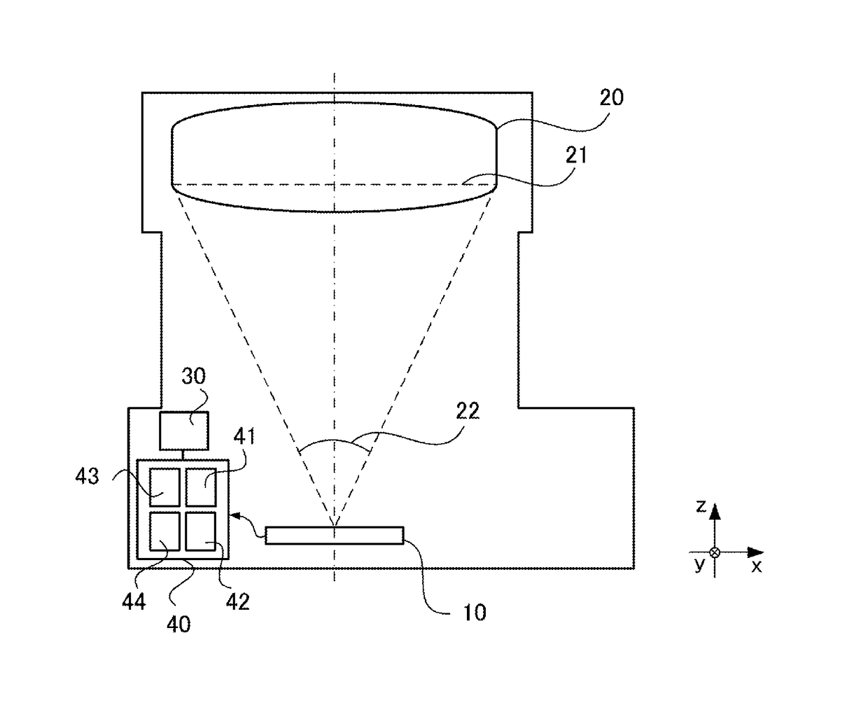
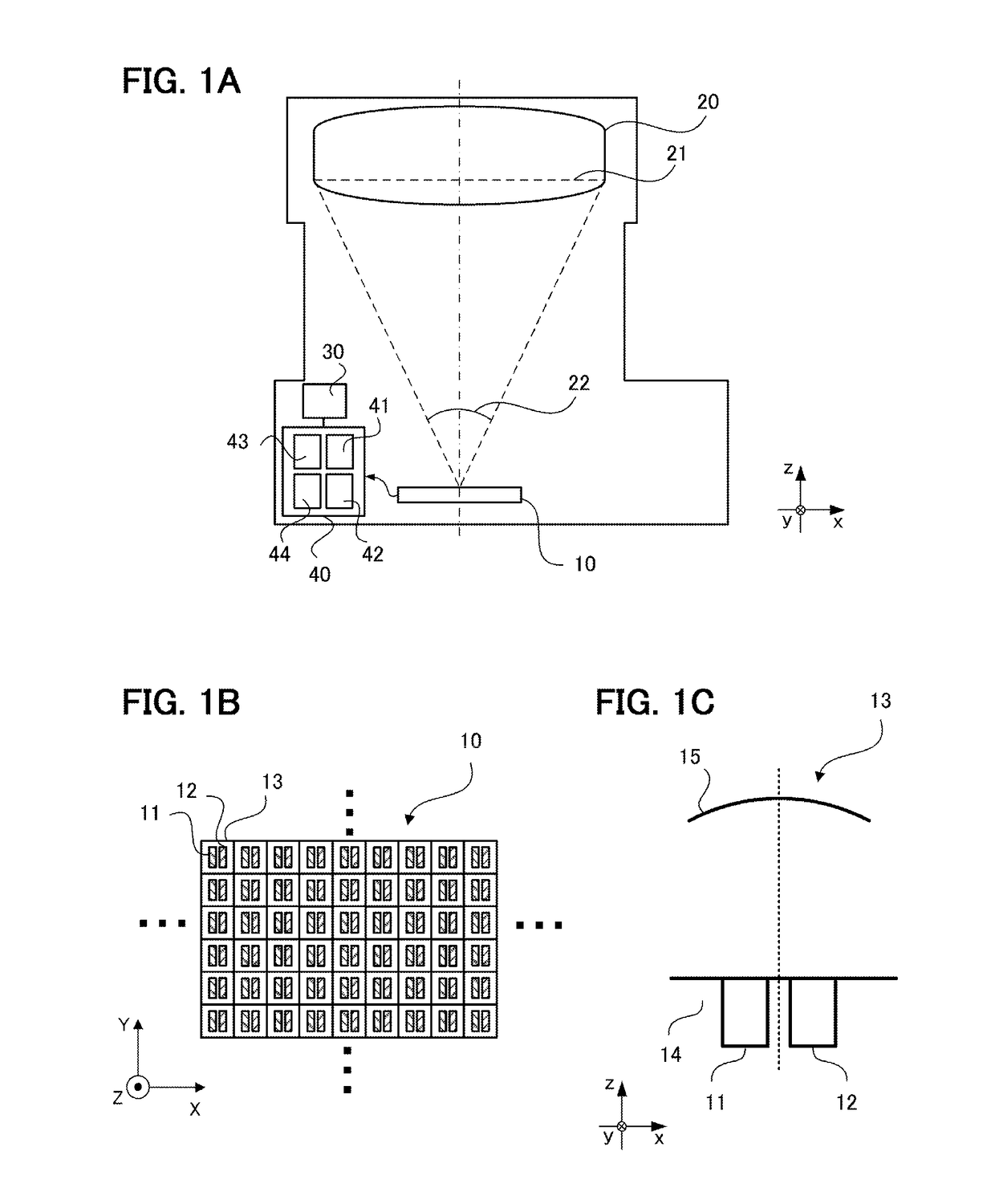
[0023]FIG. 1A is a schematic diagram of an imaging apparatus having a depth detection apparatus 40 according to the present embodiment. This imaging apparatus has an imaging device 10, an imaging optical system 20 and a recording apparatus 30, besides the depth detection apparatus 40. Furthermore, the imaging apparatus has a driving mechanism for focusing of the imaging optical system 20, a shutter, an ornamental image generation unit, and a display for imaging confirmation (e.g. liquid crystal display).

[0024]FIG. 1B is a schematic diagram depicting an example of the imaging device 10. The imaging device 10 has a plurality of depth measurement pixels 13 which includes photoelectric conversion units 11 and 12 (hereafter the depth measurement pixel is also called a “pixel”). In concrete terms, a solid-state imaging device, such as a CMOS sensor (sensor using a complementary metal-oxide semiconductor) and a CCD sensor (sensor using a charge coupled device) can be used as the imaging de...

embodiment 2

[0079]In this embodiment, it is described that pre-processing performed using a filter will reduce the calculation error and conversion error of the shift amount that is generated corresponding to the image height, whereby the depth can be measured at high-speed and high precision. Differences of this embodiment from Embodiment 1 are: the phase correction amount of the filter that is generated in the filter creation step; and the conversion coefficient used in the depth calculation step. The rest of the configuration is the same as Embodiment 1, hence the description thereof is omitted.

[0080]In the filter creation step (step S21) in FIG. 4B, the filter generation unit 44 creates an image signal correction filter based on the tentative shift amount calculated in step S10 and the image height information. For the filter, Expressions 4 to 7 or Expressions 13 to 17 or Expressions 20 to 23 can be used, and the phase component FPPj, which is a position correction amount, is different from...

embodiment 3

[0090]In this embodiment, it is described that pre-processing performed using a filter will reduce the calculation error of the shift amount and conversion error when converting the shift amount into the defocus amount, which are generated corresponding to the defocus amount and the image height, whereby the depth can be measured at high-speed and high precision. Differences of this embodiment from Embodiment 1 are: the phase correction amount of the filter that is generated in the image signal correction filter creation step; and the conversion coefficient used in the depth calculation step. The rest of the configuration is the same as Embodiment 1, hence description thereof is omitted.

[0091]In the filter creation step (step S21) in FIG. 4B, the filter generation unit 44 creates the image signal correction filter based on the tentative shift amount calculated in step S10 and the image height information. For the filter, Expressions 4 to 7 or Expression 13 to 17 or Expression 20 to ...


PUM


Abstract

A depth detection apparatus that detects depth information on a depth to an object on the basis of first and second signals corresponding to first and second pupil regions of an exit pupil, including: a first calculation unit that calculates a first shift amount between the first and second signals; a signal processing unit that generates a corrected signal by perfoiining filter processing on at least one of the first and second signals, the filter processing being performed to relatively displace the first and second signals by a displacement amount corresponding to the first shift amount; and a second calculation unit that calculates a second shift amount between the filtered first and second signals or between signals, one of which is filtered in the filter processing and the other one of which is unfiltered.

Description

TECHNICAL FIELD[0001]The present invention relates to a depth detection apparatus, an imaging apparatus and a depth detection method.BACKGROUND ART[0002]As a depth detection technique that can be applied to a digital camera, a depth detection technique to detect a depth to an object by a phase difference method, with providing a depth measurement function to a part or all of the pixels of an imaging device, is known. A pixel having the depth measurement function (hereafter called “depth measurement pixel”) includes a plurality of photoelectric conversion units which receives luminous flux that passed different regions on a pupil of an imaging optical system respectively. The depth is measured by estimating a shift amount of the image signal generated by each conversion unit, and converting the shift amount into a defocus amount using a conversion coefficient.[0003]A cause of a drop in the depth measurement accuracy is the change of profile of an image signal generated by each photoe...

Claims


Application Information

Patent Timeline
IPC IPC(8): G01C3/06H04N5/232G06T7/50H04N5/369H04N5/235
CPCG01C3/06G06T7/50H04N5/2353H04N5/3696H04N5/23293H04N5/23212G02B7/28G02B7/34H04N23/672H04N25/615H04N25/705H04N25/704G03B13/36H04N23/60H04N23/73
Inventor IKEMOTO, KIYOKATSU
Owner CANON KK
Features
  • R&D
  • Intellectual Property
  • Life Sciences
  • Materials
  • Tech Scout
  • Unparalleled Data Quality
  • Higher Quality Content
  • 60% Fewer Hallucinations
Learn More