Charged particle detector

Inactive Publication Date: 2017-11-09
RAINTREE SCI INSTR SHANGHAI
View PDF3 Cites 2 Cited by
  • Summary
  • Abstract
  • Description
  • Claims
  • Application Information

AI Technical Summary

Benefits of technology

This patent describes a new technology for detecting charged particles emitted from a sample. Compared to existing technology, this new detector has higher efficiency in detecting secondary particles, such as secondary electrons and secondary ions, and has a simpler mechanical design, resulting in lower manufacturing costs.

Problems solved by technology

However, the existing scintillators have very low ion-to-photon conversion efficiency thus very low ion detection efficiency.
In addition, even with the same energy as electrons, ions can cause larger damage to the scintillator in the detection process compared to the electrons because of their much heavier mass.

Method used


Image

  • Charged particle detector
  • Charged particle detector
  • Charged particle detector

Examples


Embodiment Construction

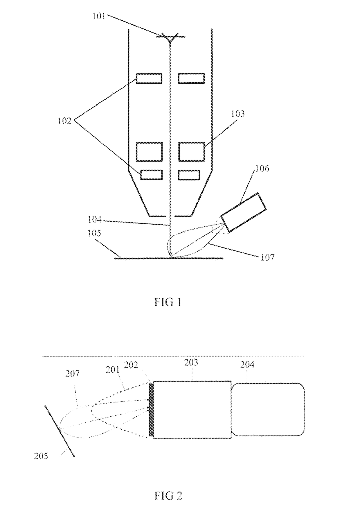
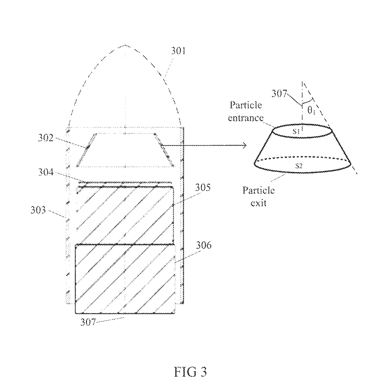
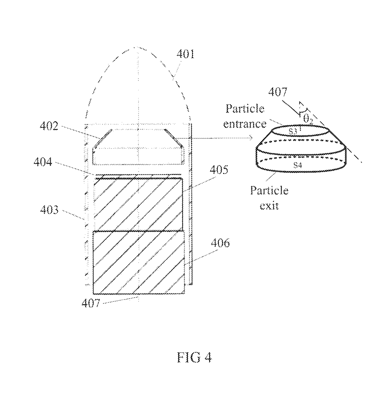
[0031]This invention provides a charged particle detector which can detect either electrons or ions by utilizing an ion-to-electron convertor between a grid electrode and an electron detection unit. The detector includes a grid electrode used to attract charged particle, an ion-to-electron convertor with a shape of particle entrance area smaller than the particle exit area, an electron detection unit and a metal shielding. In operation, the whole detector is preferably installed with an angle relative to the primary beam of a charged particle instrument, such as SEM, FIB and dual beam system containing both SEM and FIB. The grid electrode, ion-to-electron convertor and electron detection unit, preferably, are mounted coaxially, which can help to realize higher detection efficiency and also simplify the detector structure at the same time.

[0032]In order to get higher ion detection efficiency, the material of the ion-to-electron convertor as described shall have good secondary electro...


PUM


Abstract

A charged particle detector with high detection efficiency is presented in this patent. This charged particle detector contains a grid electrode used for attracting charged particles, a convertor with the shape of particle entrance area smaller than the particle exit area, which is used for converging charged particles and converting ions into electrons in the ion detection mode, an electron detection unit used for detecting secondary electrons and amplifying the signal detected, and a metal shielding. This optimized detector has a simple construction, is easy to assemble and has a low manufacturing cost.

Description

CROSS REFERENCE TO RELATED APPLICATIONS[0001]This present disclosure claims priority to Chinese patent application No. 201610285009.0 filed on May 3, 2016, the contents of which will be incorporated herein by reference in its entirety.TECHNICAL FIELD OF THE INVENTION[0002]The present invention relates to the field of charged particle imaging, analysis and processing equipments, especially relates to charged particle detection devices and charged particle instruments containing charged particle detectors.BACKGROUND OF THE INVENTION[0003]Charged particle imaging and analysis processing equipments are widely used in the semiconductor and material industry, which utilize charged particles (ion or electron) of high energy to observe or fabricate objects directly, such as, scanning electron microscope (SEM), focused ion beam (FIB) and dual beam system containing both SEM and FIB.[0004]The typical structure diagram of a FIB or SEM is shown in FIG. 1 and the working principle is as follows....

Claims


Application Information

Patent Timeline
IPC IPC(8): H01J37/244H01J37/18H01J37/28H01J37/285
CPCH01J37/244H01J37/18H01J37/28H01J37/285H01J2237/2448H01J2237/2449H01J2237/2803H01J2237/2813
Inventor LUO, HUZHANG, XU
Owner RAINTREE SCI INSTR SHANGHAI
Why Eureka
Try Eureka