
High-frequency-isolation gate driver circuit and gate circuit driving method

a technology of gate driver circuit and gate circuit, which is applied in the direction of electronic switching, pulse technique, power conversion system, etc., can solve problems such as short circuits, and achieve the effect of preventing noise current occurrence and reducing malfunctions of switching elements

Active Publication Date: 2017-11-16
KYOSAN ELECTRIC MFG CO LTD
View PDF2 Cites 5 Cited by
  • Summary
  • Abstract
  • Description
  • Claims
  • Application Information

AI Technical Summary

Benefits of technology

The present invention is about a circuit and method for driving multiple gate circuits using RF signals. The circuit is designed to isolate the drive input signals to prevent issues like noise and malfunctions. The method uses a high-frequency-isolation gate driver circuit that is suitable for frequencies from 1 to 100 MHz. Overall, the invention helps to improve the accuracy and reliability of RF signal driving for high-frequency applications.

Problems solved by technology

Therefore, there is a difference between the high-side reference potential and the low-side reference potential, and this may cause a short circuit.

Method used


Image

  • High-frequency-isolation gate driver circuit and gate circuit driving method
  • High-frequency-isolation gate driver circuit and gate circuit driving method
  • High-frequency-isolation gate driver circuit and gate circuit driving method

Examples


Embodiment Construction

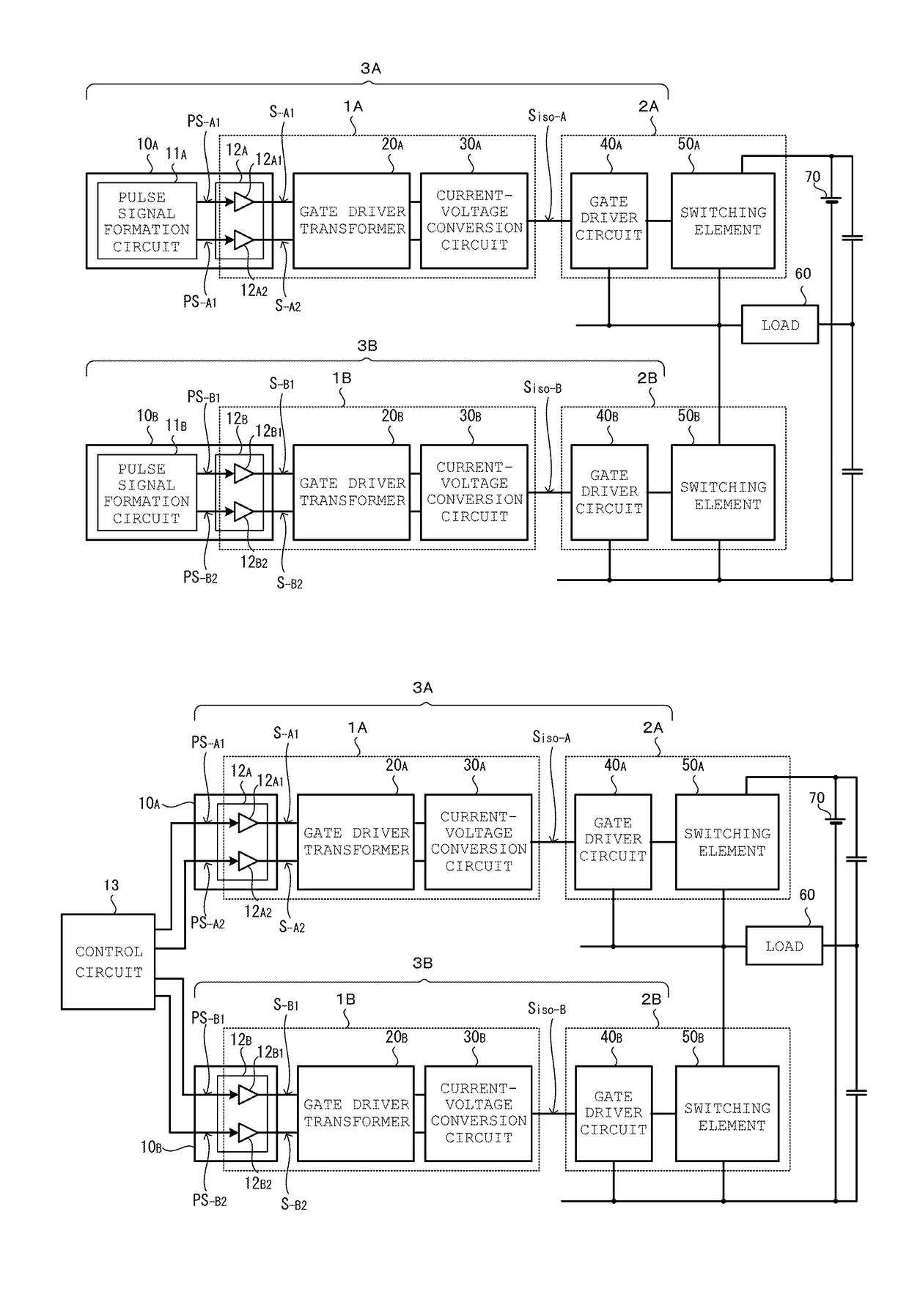
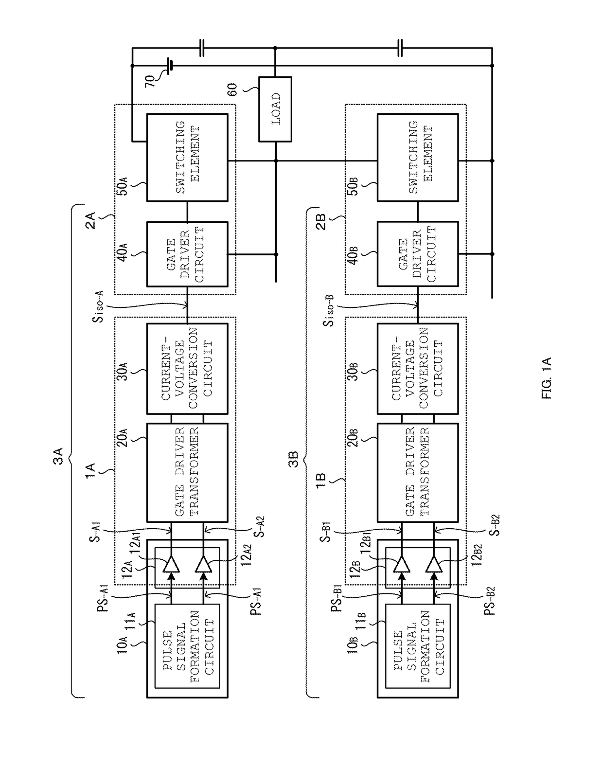
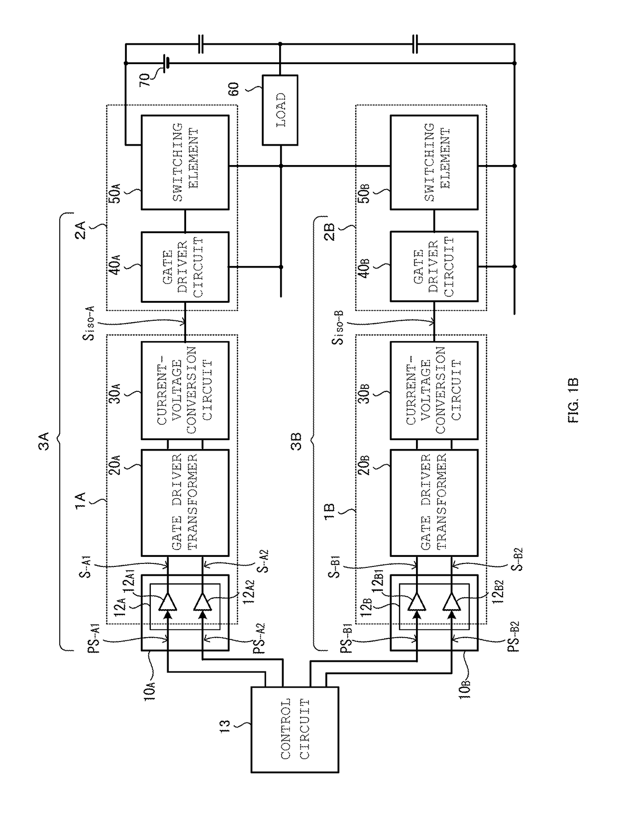
[0092]A high-frequency-isolation gate driver circuit and a gate circuit driving method will now be described, with reference to FIGS. 1 to 7.

[0093]With reference to FIG. 1, a schematic configuration of the high-frequency-isolation gate driver circuit will be described, with reference to FIGS. 2 to 6, one configuration example and an operation example of the high-frequency-isolation gate driver circuit of the present invention will be described, with reference to FIG. 7, another configuration example of the high-frequency-isolation gate driver circuit of the present invention will be described, and with reference to FIG. 8, a configuration example of the gate-driver transformer drive element provided in the high-frequency-isolation gate driver circuit of the present invention will be described.

(Configuration of the Present Invention)

[0094]FIG. 1 illustrates a schematic configuration of the high-frequency-isolation gate driver circuit of the present invention. FIG. 1(a) illustrates a ...


PUM


Abstract

In a configuration of an isolation circuit using a transformer of a high-frequency-isolation gate driver circuit in the frequency band from 1 to 100 MHz, a period for resetting the exciting current is eliminated, generation of self-resonance phenomenon after resetting is cancelled to reduce generation of noise current, and malfunctions of the switching element due to noise is prevented. In driving plural gate circuits by RF signals, exciting current is allowed to pass through a primary coil of a gate driver transformer alternately in both directions continuously all the time, in a configuration for isolating drive input signals by the gate driver transformer. Accordingly, the reset period that is required when the exciting current flows only in one way becomes unnecessary, and thus generation of self-resonance phenomenon after resetting is canceled. Then, generation of noise current caused by the self-resonance phenomenon is reduced.

Description

TECHNICAL FIELD[0001]The present invention relates to a gate driver circuit for driving a gate circuit of a semiconductor switching element and a gate circuit driving method, and it is applied to a high-frequency amplifier that delivers high-frequency power at frequencies from 1 MHz to 100 MHz.BACKGROUND ART[0002]In a power converter such as an inverter, a gate circuit of a switching element for driving a load is connected in series with a main electric power source, and a current direction of the load is switched by a bridge circuit, for example.[0003]FIG. 9(a) shows a configuration example of the power converter. This figure illustrates an example that a full bridge of switching elements 101A to 101D for switching connection between a driving source 103 and a load 104.[0004]The switching elements 101A to 101D are controlled on and off, respectively by the gate driver circuits 102A to 102D.[0005]The gate driver circuit 102A and the gate driver circuit 102C control on and off of the...

Claims


Application Information

Patent Timeline
IPC IPC(8): H03K17/16H03K7/08
CPCH03K17/162H03K7/08H02M1/08H03K17/687H03K17/567H03K17/6871
Inventor YUZURIHARA, ITSUOKUNITAMA, HIROSHI
Owner KYOSAN ELECTRIC MFG CO LTD
Learn More