
Organic light-emitting diode display device and method of driving the same

Active Publication Date: 2017-11-23
LG DISPLAY CO LTD
View PDF4 Cites 24 Cited by
  • Summary
  • Abstract
  • Description
  • Claims
  • Application Information

AI Technical Summary

Benefits of technology

The patent text describes a new way to improve the quality of OLED display devices by compensating for differences in the way pixels behave. This helps to increase the lifespan and reliability of the display, and ensures that pictures are consistent across the entire screen.

Problems solved by technology

Such an AMOLED device has advantages of low power consumption but has disadvantages in that there are deviations in characteristics such as the threshold voltage and mobility of a driving transistor for driving an organic light-emitting diode.
As a result, the magnitude of the current flowing through the organic light-emitting diode changes depending on the variations in the threshold voltage, resulting in display unevenness.
In addition, a voltage drop occurs in the high-potential voltage (VDD), such that the amount of current to drive the OLED is changed, thereby causing a luminance deviation between the pixels.
That is, since the characteristics of the transistors included in each pixel change depending on fabricating process parameters, it becomes difficult to fabricate the transistors of the AMOLED device so that all the transistors have the same characteristics.
In general, deviations in characteristics of the driving transistors at initial driving result in spots or mura on the screen, while deviations in characteristics of the driving transistors as they deteriorate with driving of the OLEDs result in problems that the lifetime of the OLED display panel is reduced or afterimages are created.
In addition, the number of components of the circuit is increased, and thus there is a disadvantage that defects are more likely to occur.

Method used


Image

  • Organic light-emitting diode display device and method of driving the same
  • Organic light-emitting diode display device and method of driving the same
  • Organic light-emitting diode display device and method of driving the same

Examples


Embodiment Construction

[0028]Advantages and features of the present disclosure and methods to achieve them will become apparent from the descriptions of exemplary embodiments hereinbelow with reference to the accompanying drawings. However, the present disclosure is not limited to exemplary embodiments disclosed herein but may be implemented in various different ways. The exemplary embodiments are provided for making the disclosure of the present disclosure thorough and for fully conveying the scope of the present disclosure to those skilled in the art. It is to be noted that the scope of the present disclosure is defined only by the claims.

[0029]The figures, dimensions, ratios, angles, the numbers of elements given in the drawings are merely illustrative and are not limiting.

[0030]Further, in describing the present disclosure, descriptions on well-known technologies may be omitted in order not to unnecessarily obscure the gist of the present disclosure. It is to be noticed that the terms “comprising,”“ha...


PUM


Abstract

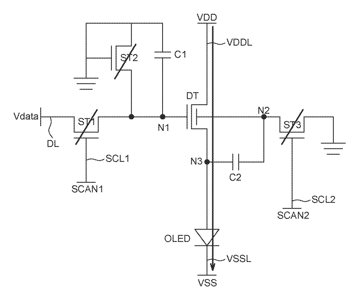
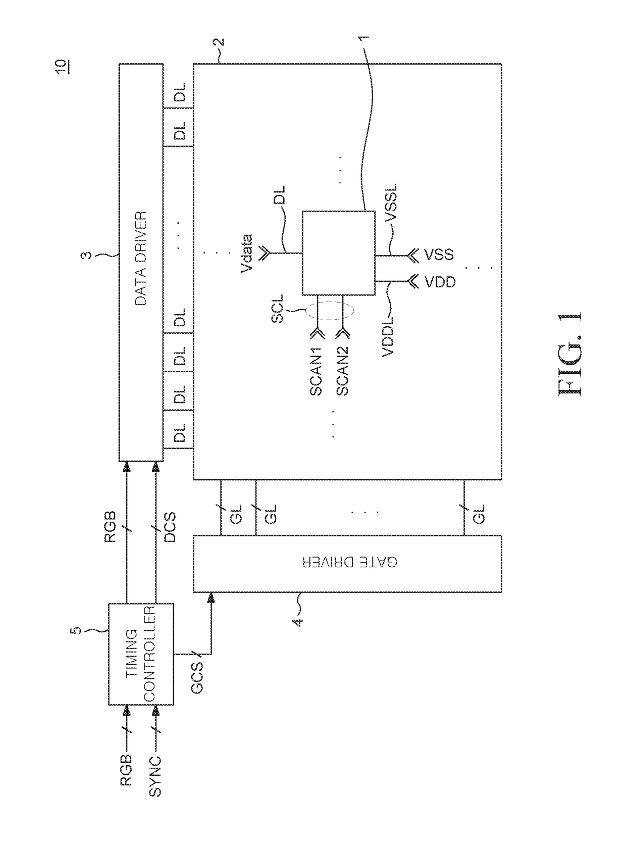
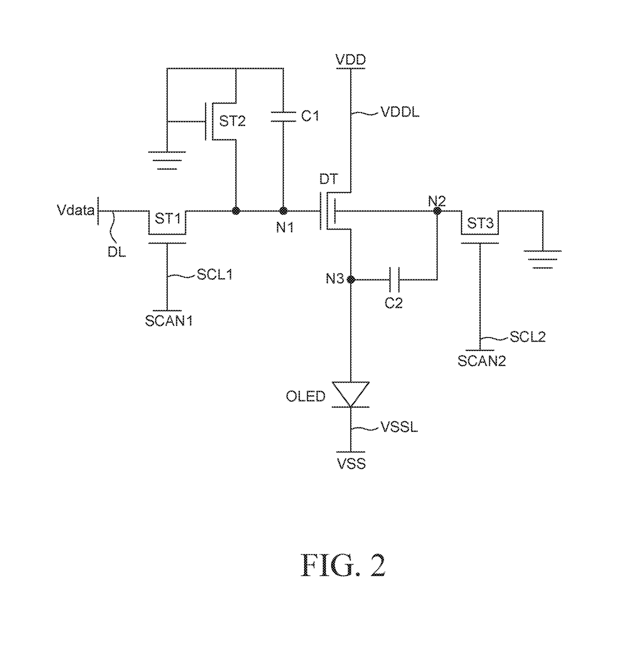
Discussed herein are an OLED display device and a method of driving the same. The OLED display device includes according to an embodiment an organic light-emitting diode; a driving transistor involved in driving the organic light-emitting diode and including a bottom gate electrode, an oxide semiconductor layer, a source electrode, a drain electrode and a top gate electrode; a first switching transistor electrically connected to the bottom gate electrode of the driving transistor and involved in transmitting a data voltage to control the driving transistor; a storage capacitor electrically connected to the bottom gate electrode and involved in charging the data voltage; a second switching transistor configured to store a threshold voltage in the storage capacitor; a compensating transistor directly connected to the top gate electrode of the driving transistor to compensate for a deviation in the threshold voltage of the driving transistor; and a compensating capacitor disposed between the source electrode of the driving transistor and a source electrode of the compensating transistor and storing the threshold voltage therein.

Description

CROSS-REFERENCE TO RELATED APPLICATIONS[0001]This application claims the priority of Korean Patent Application No. 10-2016-0062959 filed on May 23, 2016, in the Korean Intellectual Property Office, the disclosure of which is incorporated herein by reference.BACKGROUNDTechnical Field[0002]The present disclosure relates to an organic light-emitting diode (OLED) display device and a method of driving the same.Description of the Related Art[0003]Recently, various flat panel display devices capable of reducing weight and volume to address the limitations of a cathode ray tube, have been developed. Examples of flat panel display devices include a liquid-crystal display (LCD) device, a field emission display (FED) device, a plasma display panel (PDP) device, and an organic light-emitting display (OLED) device, etc.[0004]Among the flat panel display devices, the organic light-emitting display device displays an image using an organic light-emitting device that generates light as electrons a...

Claims


Application Information

Patent Timeline
IPC IPC(8): G09G3/3258H01L27/32G09G3/3291H01L27/12H01L29/786
CPCG09G3/3258G09G3/3291H01L27/3262H01L27/3265G09G2310/08H01L27/1214G09G2300/0842G09G2320/0233G09G2320/043G09G2320/0257H01L29/78648G09G2300/0871G09G3/3233H01L27/1225H01L27/1255G09G2300/0852G09G2300/0861G09G2310/0262H10K59/1213H10K59/1216
Inventor JEON, CHANGHOONRHA, SUNGHOON
Owner LG DISPLAY CO LTD
Learn More