
Liquid-cooled heat dissipation apparatus

a heat dissipation apparatus and liquid-cooled technology, which is applied in lighting and heating apparatus, cooling/ventilation/heating modifications, basic electric elements, etc., can solve the problems of reduced working fluid inside the water-cooled device, reduced heat generation by the heat generating components, etc., to achieve the effect of high flexibility and water supply

Active Publication Date: 2017-11-23
KUAN DING TECH
View PDF2 Cites 15 Cited by
  • Summary
  • Abstract
  • Description
  • Claims
  • Application Information

AI Technical Summary

Benefits of technology

The present invention is a liquid-cooled heat dissipation apparatus with a detachable reservoir tank and a water pump connected to the tank and cooling head for circulation of the cooling liquid. The apparatus has separate reservoir and pipeline exhaust, making it flexible for different cooling needs. The reservoir tank is made of transparent material for easy water level observation, and its configuration can be modified for different modularizations. The technical effects of the present invention are independent water reservoir, pipeline exhaust, easy water supply, and flexibility.

Problems solved by technology

With the rapid development of electronic industry, the amount of heat generated by the heat generating components, such as central processors and graphic processors etc., inside electronic products, also increases continuously in such a way that conventional heat sinks may even be insufficient for the cooling of such heat generation components and water-cooled heat sinks equipped with liquid cooling circulation effect are required to effectively dissipate the heat generated by the heat generating components.
However, after a long period of use, the working fluid inside the water-cooled device reduces; therefore, the question on how to allow the water-cooled device having the water supply effect and such water supply process having facilitated water supply without wetting other components is one of the key issues for improvement.
Consequently, the question on how to deal with different types of specifications in order to cope with different corresponding requirements is also another key issue for improvement of a water-cooled heat sink.

Method used


Image

  • Liquid-cooled heat dissipation apparatus
  • Liquid-cooled heat dissipation apparatus
  • Liquid-cooled heat dissipation apparatus

Examples


Embodiment Construction

[0024]The following provide a detailed description on the technical content of the present invention along with the accompanied drawings. However, it shall be understood that the drawings are provided for illustration purposes only rather than to limit the scope of the present invention.

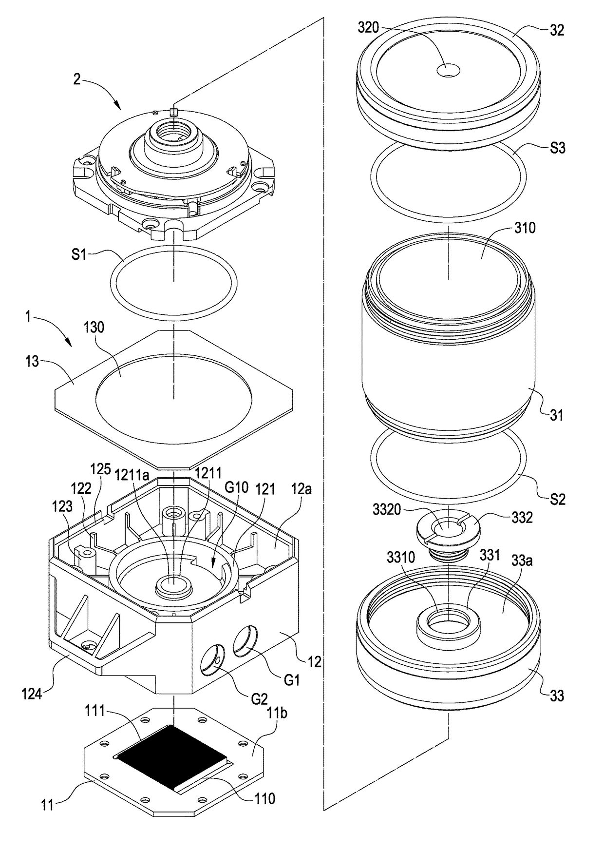
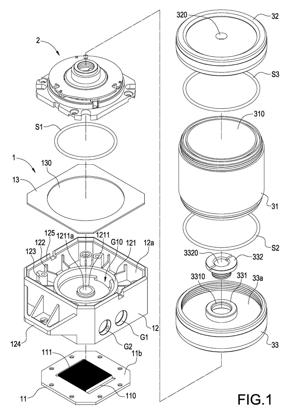
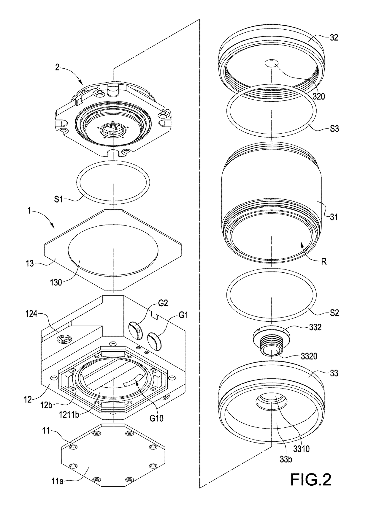
[0025]As shown in FIG. 1 to FIG. 7, the present invention provides a liquid-cooled heat dissipation apparatus, comprising a water cooling module 1 and a reservoir tank 3, wherein the reservoir tank 3 is detachably stacked onto the water cooling module 1, and the water cooling module 1 includes a water pump set 2. The water cooling pump assembly 2 is arranged between the water cooling module 1 and the reservoir tank 3.

[0026]The water cooling module 1 includes a base 12 and a heat exchange unit 11 connected to the base 12. The two upper and lower sides of the base 12 include an upper slot 12a and a lower slot 12b formed thereon respectively. In addition, an outer circumferential wall at one side of the...


PUM


Abstract

A liquid-cooled heat dissipation apparatus includes a water cooling module (1), a water pump set (2) and a reservoir tank (3). The water cooling module (1) includes a heat exchange unit (11) and a base (12) having a pump receiving slot (121) and a heat exchange chamber (T). The base (12) includes a water inlet channel (G1), drainage channel (G2) and first channel (G10). The water pump set (2) is arranged inside the pump receiving slot (121) and includes a rotor assembly (21) and a blade assembly (23). The blade assembly (23) is attached onto the rotor assembly (21) and includes a second channel (G20). The reservoir tank (3) is detachably stacked onto the water cooling module (1) and includes a water containing chamber (R) and a water supply channel (G3) formed thereon. Accordingly, the apparatus achieves the effects of independent reservoir, readily water supply and pipeline exhaust simultaneously.

Description

BACKGROUND OF THE INVENTIONField of the Invention[0001]The present invention is related to a heat dissipation apparatus, in particular, to a liquid-cooled heat dissipation apparatus used for increasing the overall cooling performance.Description of Related Art[0002]With the rapid development of electronic industry, the amount of heat generated by the heat generating components, such as central processors and graphic processors etc., inside electronic products, also increases continuously in such a way that conventional heat sinks may even be insufficient for the cooling of such heat generation components and water-cooled heat sinks equipped with liquid cooling circulation effect are required to effectively dissipate the heat generated by the heat generating components. A traditional water-cooled device comprises a water cooling head, a water cooling manifold and a water pump connected to each other. The internal of the water cooling head, the internal of the water cooling manifold a...

Claims


Application Information

Patent Timeline
IPC IPC(8): H05K7/20
CPCH05K7/20263H05K7/20254H05K7/20272H01L23/473F28D15/00H01L23/552F28D2021/0029
Inventor PAN, KUAN-DA
Owner KUAN DING TECH
Learn More