Gas distribution structure for distillation column and control method thereof

a technology of gas distribution structure and distillation column, which is applied in the direction of chemistry apparatus and processes, separation processes, dispersed particle separation, etc., to achieve the effect of effective adjustment and control of gas distribution ratio, improving gas distribution precision, and improving rectification precision

Inactive Publication Date: 2017-11-30
TIANJIN AOZHAN XINGDA TECH
View PDF11 Cites 8 Cited by
  • Summary
  • Abstract
  • Description
  • Claims
  • Application Information

AI Technical Summary

Benefits of technology

[0050]The present invention also proposes a method for realizing gas distribution and control of a distillation column by using the gas distribution structure. The gas distribution and control of the distillation column are realized through a coordination effect of the circulation pumps, the adjusting valves, the flow meters and the control system in the gas distribution structure of the present invention. The control system controls the circulation pumps and the adjusting valves. The liquid flow meters and the gas flow meters feed back current technological parameters to the control system. The control system issues a command for controlling the circulation pumps and the adjusting valves again according to a set technological control target until the fed-back technological parameters meet the technological control target. In the entire control process, the change of a liquid flow of each layer of pressur...

Problems solved by technology

The dividing wall type distillation column produces more operating degrees of freedom due to complexity of its structure and process, so energy conservation and acquisition of high-purity products are not easy and require internal variables of a system to have stronger controllability.
Thus, a problem about controlling the division of the dividing wall type distillation column becomes a major factor hindering its industrial application.
Since the adjustment for distribution of the gas on both sides of the dividing wall involves a series of calculation processes such as complex hydraulic calculation, dynamic simulation of operating parameters, analysis of a gas-liquid two-phase flow field, etc., the adjustment and control for distribution of the gas on both sides of the dividing wall is quite difficult.
Since changes in feed compositions and states, a liquid distribution proportion and the like may become important factors affecting the distribution of the gas, a flow ratio of gases automatically distributed to both sides of the dividing wall often cannot reach an optimal operation condition of the dividing wall column.
The pressure drops of both sides of the dividing wall are changed by using the internal member or placing the division wall eccentrically, so that the operating flexibility and the sensitivity are low, and the device cannot operate stably for a long period due to mechanical wear caused by movement of the dividing wall.
The technical solution has major defects that: firstly, gas phase redistribution apparatuses need to be arranged in the column when the gas phase is led out and the gas phase enters the column again, causing an increase of the column height and the complexity of internal parts; secondly, for the dividing wall column with relatively high production and processing capabilities, diameters of the bypass gas phase pipelines 54a and 54b may be very large, and installation and maintenance of relevant components are inconvenient; thirdly, for the bypass gas phase pipelines 54a and 54b provided with the adjusting valves 56a and 56b and the flow meters 58a and 58b, not only the column height is increased, but also a characteristic of gas flowing pressure drop becomes quite complicated; ...

Method used


Image

  • Gas distribution structure for distillation column and control method thereof
  • Gas distribution structure for distillation column and control method thereof
  • Gas distribution structure for distillation column and control method thereof

Examples


embodiment 1

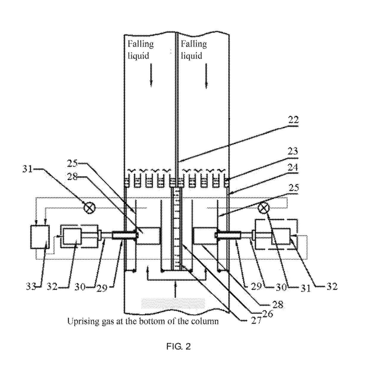
[0104] the gas flow (of the gas flow meter FIC02) in the left mass transfer region of the dividing wall needs to be reduced by 30%.

[0105]Firstly, a left circulation pump P01 is started; a left adjusting valve V10 is started by the DCS; a valve opening is adjusted to 50%; the liquid level H of the column tray is adjusted by pressure drops of three layers of column trays on the left side; the liquid level of the column tray is gradually increased from a normal value 50 mm to 100 mm; 50% of the sieve holes 17 in the cover hoods 6 are submerged by the liquid; the pressure drops of the three layers of column trays are monitored by DCS through PIC01 (Pressure Identify & Control, pressure gauge), PIC02, PIC03 and PIC09, the pressure drop of each layer is gradually increased to 120 Pa; the opening of the adjusting valve and the gas phase flow are jointly adjusted; the gas flow V1 on the left side is decreased rapidly; readings of TIC01 and TIC02 are monitored; after the FIC02 shows that the...

embodiment 2

[0108] the gas flow V1 (of the gas flow meter FIC02) in the left mass transfer region of the dividing wall needs to be reduced by 20%, and the gas flow V2 (of the gas flow meter FIC01) on the right side of the dividing wall is increased by 20%.

[0109]Firstly, a left circulation pump P01 is started by the DCS; a left adjusting valve V10 is started; the valve opening is adjusted to 35%; the liquid level H of the column tray is adjusted by pressure drops of three layers of column trays on the left side; the liquid level H of the column tray is increased from a normal value 50 mm to 85 mm, 35% of the sieve holes 17 in the cover hoods 6 are gradually submerged by the liquid; the pressure drops of the three layers of column trays are detected by PIC01, PIC02, PIC03 and PIC09, the pressure drop of each layer of three layers of column trays is gradually increased to 80 Pa; the opening of the adjusting valve and the gas phase flow are jointly adjusted; the gas flow V1 on the left side is decr...

embodiment 3

[0112] adjustment and control objective: the gas flow V1 (of the gas flow meter FIC02) in the left mass transfer region of the dividing wall needs to be reduced by 5%.

[0113]Firstly, a left circulation pump P01 is started by the DCS; a left adjusting valve V10 is started; the valve opening is adjusted to 15%; the liquid level H of the column tray is adjusted by pressure drops of three layers of column trays on the left side; the liquid level H of the column tray is increased from a normal value 50 mm to 65 mm, 15% of the sieve holes 17 in the cover hoods 6 are submerged by the liquid; the pressure drops of the three layers of column trays are monitored by PIC01, PIC02, PIC03 and PIC09, the pressure drop of each of the three layers of column trays is increased to 50 Pa; the opening of the adjusting valve and the gas phase flow are jointly adjusted; the gas flow V1 on the left side is decreased rapidly; readings of TIC01 and TIC02 are monitored at the same time; after the FIC02 shows t...


PUM


Abstract

The present invention discloses a gas distribution structure for a distillation column. Pressure drop adjusting column tray assemblies are arranged in a left mass transfer region and a right mass transfer region along a column height direction. The gas distribution structure includes column trays, gas-rising pipes, downcomers and cover hoods, wherein a gas flow meter is arranged in a pipe of any gas rising pipe; a feeding port and a liquid collecting port are formed in a column wall; a liquid flow meter, an adjusting valve and a circulation pump are arranged on a circulation pipeline between each liquid collecting port and each feeding port; technological parameters are transmitted to a control system; and the circulation pumps and the adjusting valves are controlled by the control system

Description

CROSS-REFERENCE TO RELATED APPLICATIONS[0001]This application is a continuation of International Patent Application No. PCT / CN2015 / 076403 with a filing date of Apr. 13, 2015, designating the United States, now pending, and further claims priority to Chinese Patent Application No. 201510086163.0 with a filing date of Feb. 17, 2015 and Chinese Patent Application No. 201520114631.6 with a filing date of Feb. 17, 2015. The content of the aforementioned applications, including any intervening amendments thereto, are incorporated herein by reference.TECHNICAL FIELD[0002]The present invention relates to a gas flow distribution and control system for a distillation column in chemical engineering, and particularly relates to a steady gas flow distribution and flow control method with high operational flexibility for gas-liquid mass transfer of a thermal coupling process or device.BACKGROUND OF THE PRESENT INVENTION[0003]A rectification technological process is a high energy-consumption opera...

Claims


Application Information

Patent Timeline
IPC IPC(8): B01D3/14B01D3/32B01D53/18B01D3/42B01D3/16B01D3/28
CPCB01D3/141B01D3/32B01D3/28B01D53/185B01D3/163B01D3/42B01D3/14B01D3/4261B01D3/20
Inventor ZHANG, BINGLI, JIANMINGRUAN, JIEZHANG, CHUNLU
Owner TIANJIN AOZHAN XINGDA TECH
Why Eureka
Try Eureka