
Three-dimensional printer

a three-dimensional printer and printer technology, applied in the field of three-dimensional printers, can solve the problems of affecting affecting the circulation of materials in the material supply device, etc., and achieves the effects of enabling long-time automated lamination molding work, high processing accuracy, and smooth powder layer formation

Active Publication Date: 2017-12-07
SODICK CO LTD
View PDF13 Cites 65 Cited by
  • Summary
  • Abstract
  • Description
  • Claims
  • Application Information

AI Technical Summary

Benefits of technology

The patent aims to provide a method for creating a smooth layer of powder using recycled non-sintered material powder. It also aims to enable long automated lamination molding work while maintaining high processing accuracy.

Problems solved by technology

However, while non-sintered material powder which is recycled along with impurities is discharged into the bucket outside the powder retaining wall, has the impurities removed therefrom, and is then supplied to the material supply device again, for example, there is concern that powder grains may absorb ambient moisture in the bucket partially due to an ambient environment of the three-dimensional printer, are likely to stick to each other as an aggregate, and degrade circulation of the material in the material supply device.
Accordingly, there is a likelihood that long-time automated lamination molding work will be hindered.

Method used


Image

  • Three-dimensional printer
  • Three-dimensional printer
  • Three-dimensional printer

Examples


Embodiment Construction

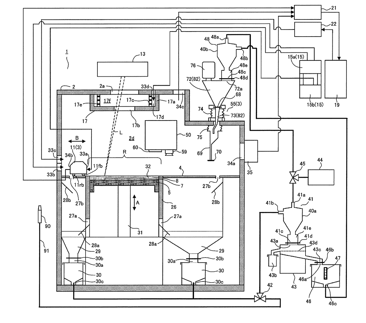
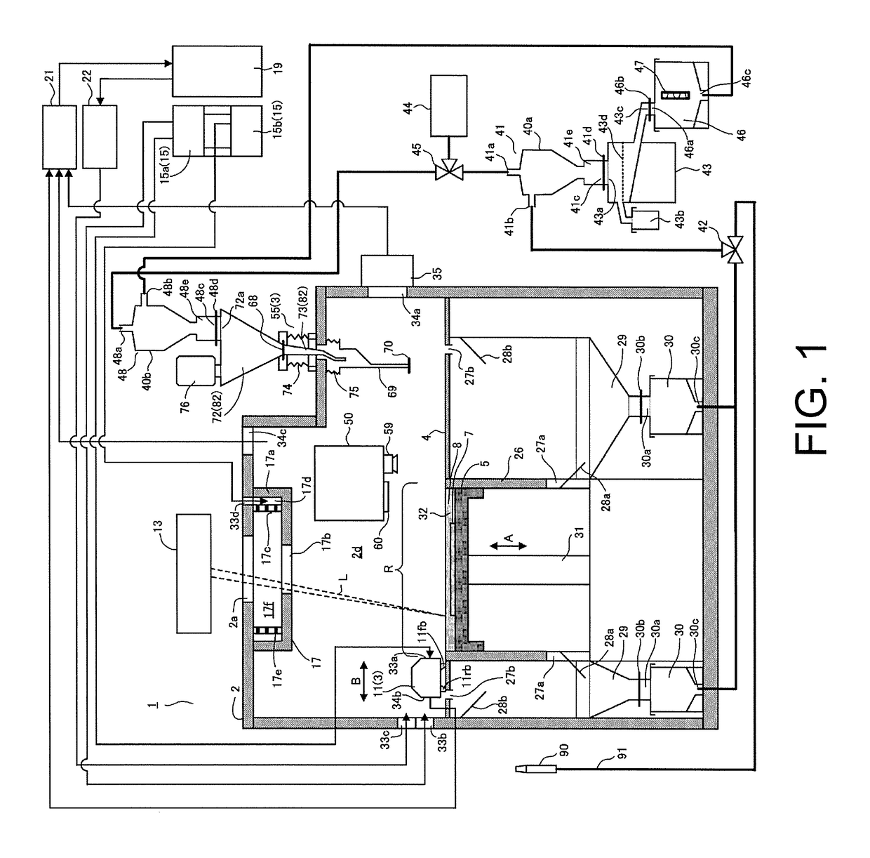
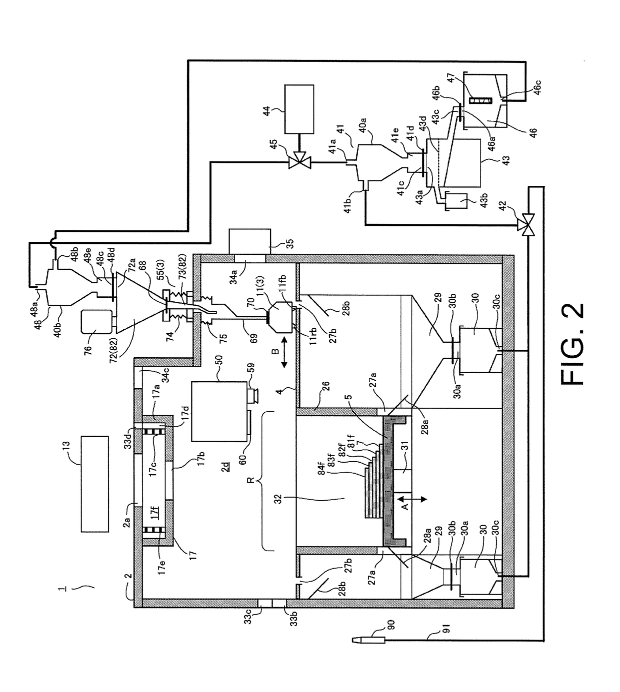
[0013]Hereinafter, an embodiment of the invention will be described with reference to the accompanying drawings. Various features described in the following embodiment can be combined with each other. In FIG. 2, an inert gas supply and discharge system is omitted.

[0014]As illustrated in FIG. 1, a three-dimensional printer 1 includes a base 4, a chamber 2 that covers a necessary molding region R on the base 4, a table 5 that is disposed in the molding region R and moves vertically, a material supply device 3 that supplies material powder to the molding region R, and a laser beam irradiation unit 13 that irradiates the material powder with a laser beam L to sinter the material powder.

[0015]The chamber 2 is filled with inert gas at a predetermined concentration. The table 5 is driven by a table driving mechanism 31 such that it is movable in an up-down direction (in a direction of arrow A in FIG. 1). The molding region R is disposed on the table 5. The material supply device 3 includes...


PUM


Abstract

A three-dimensional printer (1) includes a material supply device (3) that supplies material powder to a table which is movable vertically, a powder retaining wall (26) that surrounds the table and retains the material powder, a material-recovery bucket (30) that accommodates excess material powder and impurities discharged from the powder retaining wall, an impurity removing device (43) that removes the impurities from the material powder, and a material drying device (47) that dries the material powder. The material powder from which the impurities have been removed and which has been dried is returned and recycled to the material supply device.

Description

CROSS-REFERENCE TO RELATED APPLICATION[0001]This application claims the priority benefit of Japan Application no. 2016-109991, filed on Jun. 1, 2016. The entirety of the above-mentioned patent application is hereby incorporated by reference herein and made a part of this specification.BACKGROUND OF THE INVENTIONField of the Invention[0002]The present invention relates to a three-dimensional printer. Particularly, the present invention relates to a three-dimensional printer that recovers an excess of material powder supplied into a chamber, removes impurities therefrom, and then supplies the resultant material powder to the chamber again.Description of Related Art[0003]In lamination molding of metal using a laser beam, a desired three-dimensional object including a plurality of sintered layers is formed by repeating operations of supplying material powder onto a table, which is disposed in a chamber as a build chamber filled with inert gas and is movable vertically, to form a powder ...

Claims


Application Information

Patent Timeline
IPC IPC(8): B22F3/105B33Y30/00B33Y50/02
CPCB22F3/1055B22F2003/1057B33Y50/02B33Y30/00B33Y40/00B29C64/35B29C64/255B29C64/357B29C64/307Y02P10/25B22F10/322B22F10/77B22F12/90B22F10/28B22F10/73Y02P10/20
Inventor KAWADA, SHUICHIOKAZAKI, SHUJI
Owner SODICK CO LTD
Learn More