Suspension device and suspension control unit

Inactive Publication Date: 2017-12-07
KYB CORP
View PDF10 Cites 8 Cited by
  • Summary
  • Abstract
  • Description
  • Claims
  • Application Information

AI Technical Summary

Benefits of technology

This patent is about a suspension system and control unit that can improve the quality of vehicles without using a highly responsive device. Its technical effect is to make vehicles ride smoother and more comfortably.

Problems solved by technology

The solenoid has a response delay, so that it is difficult to control the electromagnetic valve with high accuracy at a frequency band of around 10 Hz.
For this reason, using a suspension device provided with an electromagnetic valve, it is difficult to improve a vehicle ride quality.

Method used


Image

  • Suspension device and suspension control unit
  • Suspension device and suspension control unit
  • Suspension device and suspension control unit

Examples


first embodiment

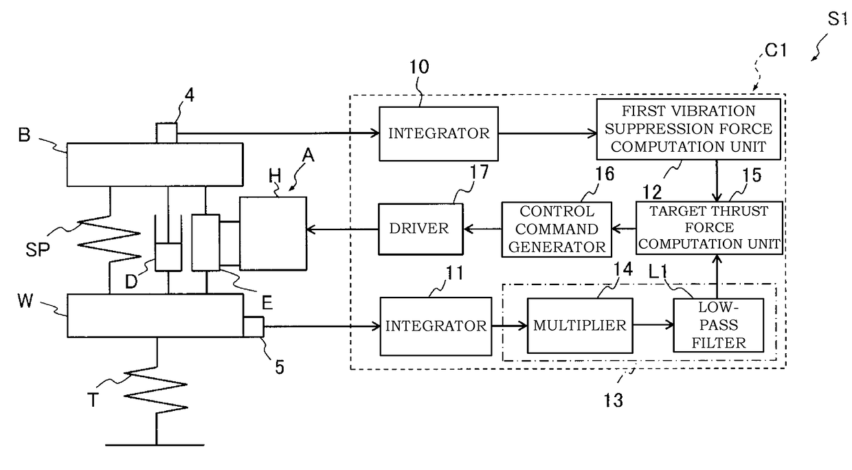
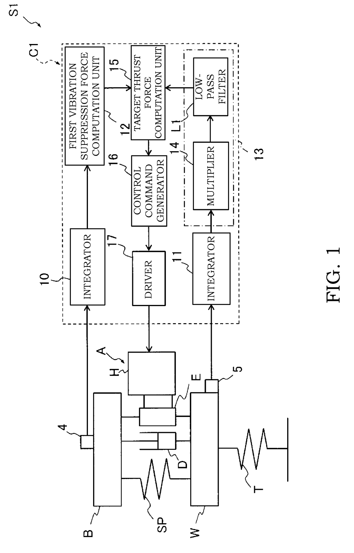
[0028]A suspension device 51 according to a first embodiment of the present invention will be described with reference to FIG. 1.

[0029]The suspension device 51 includes an actuator A interposed between a sprung member B as a vehicle chassis and an unsprung member W as a traveling wheel to generate a thrust force, a passive damper D interposed between the sprung member B and the unsprung member W in parallel with the actuator A, and a controller C1 as a suspension control unit for controlling the actuator A.

[0030]The actuator A includes an extensible / contractible body E provided with a cylinder (not shown), a piston movably inserted into the cylinder to partition the cylinder into an extension-side chamber and a contraction-side chamber, and a rod movably inserted into the cylinder and connected to the piston, and a hydraulic pressure unit H that supplies and distributes fluid to the extension-side chamber and the contraction-side chamber to extensibly or contractibly drive the exten...

second embodiment

[0079]Next, a suspension device S4 and a controller C4 as a suspension control unit according to a second embodiment of the invention will be described with reference to FIG. 10. In the following description, differences from the first embodiment will be focused. In addition, like reference numerals denote like elements as in the first embodiment, and they will not be described repeatedly.

[0080]As illustrated in FIG. 10, the suspension device S4 includes an actuator A interposed between a sprung member B as a vehicle chassis and an unsprung member W as a traveling wheel to generate a thrust force, a damper D interposed between the sprung member B and the unsprung member W in parallel with the actuator A, and a controller C4 as a suspension control unit for controlling the actuator A.

[0081]Similar to the first embodiment, the actuator A includes an extensible / contractible body E provided with a cylinder (not shown), a piston movably inserted into the cylinder to partition the cylinde...


PUM


Abstract

A suspension device includes an actuator capable of generating a thrust force and a controller. The controller includes a first vibration suppression force computation unit configured to obtain a first vibration suppression force from a vertical velocity of a sprung member, a second vibration suppression force computation unit configured to obtain a second vibration suppression force from a vertical velocity of the unsprung member or a relative velocity between the sprung member and the unsprung member, a low-pass filter having a breakpoint frequency between a sprung resonance frequency and an unsprung resonance frequency and processing a signal in the course of obtaining the second vibration suppression force using the second vibration suppression force computation unit, and a target thrust force computation unit configured to obtain a target thrust force of the actuator on the basis of the first vibration suppression force and the second vibration suppression force.

Description

TECHNICAL FIELD[0001]The present invention relates to a suspension device and a suspension control unit.BACKGROUND ART[0002]As such a type of the suspension device, for example, there is known a suspension device provided with a hydraulic cylinder interposed between a sprung member as a vehicle chassis and an unsprung member as a traveling wheel to actively exert a thrust force and a controller for controlling the hydraulic cylinder, the suspension device serving as an active suspension device.[0003]The controller obtains a vertical velocity of the sprung member by processing a vertical acceleration of the sprung member detected by an acceleration sensor with a low-pass filter and obtains a required thrust force of the hydraulic cylinder necessary to suppress a vibration in the sprung member by multiplying the vertical velocity by a gain. In addition, the controller processes a vertical acceleration of the unsprung member with a band-pass filter and obtains a required thrust force o...

Claims


Application Information

Patent Timeline
IPC IPC(8): B60G17/018F16F9/46B60G17/048B60G17/08
CPCB60G17/018B60G17/08B60G2204/62F16F9/461B60G2400/206B60G17/048B60G17/015B60G2202/414B60G2400/202B60G2600/60B60G2202/30B60G2202/416B60G2400/102B60G2600/604B60G2600/182B60G2800/9123B60G17/0157F16F9/46F16F15/02
Inventor MASAMURA, TATSUYA
Owner KYB CORP
Why Eureka
Try Eureka