Resonator, and an aircraft fitted with the resonator

a technology of resonators and resonators, which is applied in the direction of rotorcraft, speed/acceleration/shock instrument details, and acceleration measurement using interia forces. it can solve the problems of large modifications, attenuation of vibratory phenomena, and vibration problems on aircraft. it can improve the performance of a damped resonator, and reduce the reaction time of the resonator

Active Publication Date: 2017-12-07
EUROCOPTER
View PDF2 Cites 7 Cited by
  • Summary
  • Abstract
  • Description
  • Claims
  • Application Information

AI Technical Summary

Benefits of technology

[0056]Specifically, the resilient member presents a stiffness coefficient that is not negligible. In addition, the first electric coil serves to damp the movement of the seismic mass. Finally, the actuator serves to exert a dynamic force on the seismic mass.
[0058]Introducing the actuator that is electrically powered in variable manner enables the performance of a damped resonator to be improved. Controlling the actuator makes it possible in real time to adapt the resonator to the vibration to which a structure is subjected.
[0059]This improvement requires relatively little power for electrically powering the actuator. In addition, the reaction time of the resonator can be minimized, thus enabling the resonator to combat unsteady phenomena.
[0060]In addition, the resonator may provide damping to a carrier structure that is subjected to vibration, which damping is optimized compared with a damper that does not have an actuator controlled as a function of two measured parameters.
[0062]The first gain makes it possible to shift the vibratory mode of the resonator relative to the frequency at which the antiresonance that is to be produced occurs. This shift tends to increase the stability range of the resonator. The second gain may then be maximized in order to optimize the damping that is provided.

Problems solved by technology

In addition to forced excitations, another vibratory phenomenon can give rise to vibratory problems on an aircraft.
Such a problem lies in the attenuation of vibratory phenomena induced by the aeroelastic instabilities to which an aircraft is subjected in flight.
By way of example, such instability can result from coupling between the vibratory modes of a bladed rotor and the vibratory modes of the carrier structure supporting the rotor.
An instability appearing on an existing aircraft thus requires structural modifications to the rotor and / or to the carrier structure, which modifications may be considerable.
In the event of a modification to the carrier structure of an aircraft, it can nevertheless be difficult to adapt a damped resonator.
Unfortunately, certain aircraft may have a main rotor that rotates at a speed setpoint that can vary during a flight.
This situation makes the means for compensating the resulting aerodynamic instabilities more complicated, since for such aircraft it is necessary to attenuate the “broadband” vibration generated by the rotation of the main rotor.
An ordinary damped resonator can thus be less effective in this context.
Nevertheless, the damping provided is limited because of its intrinsic instability.
If the resonator is adjusted to counter the vibration exerted on a structure by using an actuator and the dynamic amplification of the seismic mass for generating a force is large, then the operation of the resonator can become unstable and uncontrollable.

Method used


Image

  • Resonator, and an aircraft fitted with the resonator
  • Resonator, and an aircraft fitted with the resonator
  • Resonator, and an aircraft fitted with the resonator

Examples


Embodiment Construction

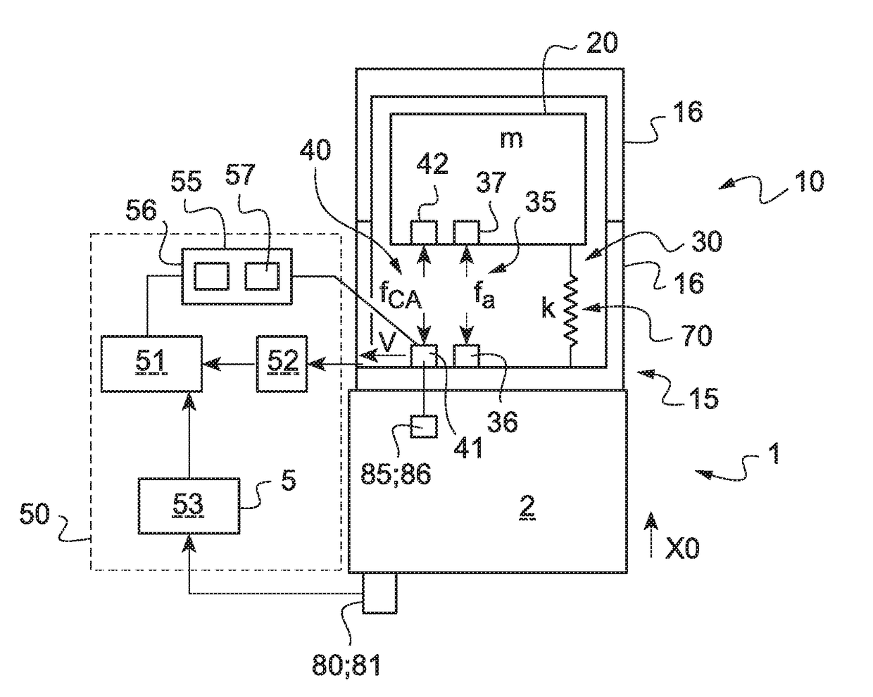
[0115]FIG. 1 shows an aircraft 1 of the invention. The aircraft is provided with a structure referred to as a “carrier” structure 2. The carrier structure 2 is subjected to vibration tending to move the carrier structure along a direction X0.

[0116]Under such circumstances, the aircraft 1 has a resonator 10 of the invention for minimizing this vibration, at least at certain frequencies.

[0117]The resonator 10 comprises a support 15 secured to the carrier structure 2 by conventional means that are not shown. For example, the support 15 may be screw-fastened, adhesively-bonded, welded, or indeed riveted to the carrier structure.

[0118]The support 15 may represent a casing defining a hollow inside space of the resonator 10. Under such circumstances, the support may comprise a single mechanical part 16 or a plurality of parts 16 that are fastened to one another.

[0119]Furthermore, the resonator 10 is provided with a seismic mass 20. The term “seismic mass” is used to mean a mechanical unit ...


PUM


Abstract

A resonator having a support and a seismic mass. Movement means include a first electromagnetic assembly comprising a first electric coil that is not electrically powered. An actuator is connected to a processor unit, the processor unit electrically powering the actuator with adjustable electrical power. A resilient member is interposed between said seismic mass and said support.

Description

CROSS-REFERENCE TO RELATED APPLICATIONS[0001]This application claims priority to European patent application No. FR 16 00893 filed on Jun. 2, 2016, the disclosure of which is incorporated in its entirety by reference herein.BACKGROUND OF THE INVENTION(1) Field of the Invention[0002]The present invention relates to a resonator and to an aircraft fitted with the resonator.[0003]The present invention relates to mechanisms seeking to reduce a level of vibration. In particular, the present invention relates to mechanisms seeking to reduce vibrations induced by aeroelastic instabilities that result from coupling between the vibratory modes of the carrier structure of an aircraft and the vibratory modes of a rotor of the aircraft. Such a mechanism can possibly be used to treat excitations of a helicopter tail boom, and in particular to treat the phenomenon known as “tail shake”. The invention provides such a mechanism and an aircraft provided with such a mechanism.(2) Description of Relate...

Claims


Application Information

Patent Timeline
Patent Type & Authority Applications(United States)
IPC IPC(8): B64C27/00G01P1/00G01P15/08
CPCB64C27/001G01P1/003B64C2027/005B64C2027/004G01P15/08F16F7/1005F16F15/03F16F7/1011F16F15/002F16F15/02
Inventor INQUIETE, GUILLAUMECRANGA, PAULCHESNE, SIMON
Owner EUROCOPTER
Why Eureka
Try Eureka