
System and method for intake manifold pressure control

a technology of intake manifold and pressure control, which is applied in the direction of electrical control, machines/engines, output power, etc., can solve the problems of difficult control of engine torque during intake manifold pump down, increased pressure of intake manifold, and increased torque of cylinders, so as to achieve accurate control of engine torque, low demand torque, and increased torque

Active Publication Date: 2017-12-14
FORD GLOBAL TECH LLC
View PDF8 Cites 17 Cited by
  • Summary
  • Abstract
  • Description
  • Claims
  • Application Information

AI Technical Summary

Benefits of technology

The patent describes a method for controlling engine torque and reducing emissions during cylinder reactivation. By prepositioning engine volumetric efficiency actuators and controlling intake manifold pressure, the engine can operate with a desired intake manifold pressure in a short amount of time after reactivating engine cylinders. This approach may improve torque control and reduce emissions by not exposing the engine's catalyst to fresh air. Additionally, it may improve engine responsiveness to torque request increases after reactivating engine cylinders.

Problems solved by technology

Intake manifold pressure may rise after closing the intake valves because of the absence of air flow through cylinders and because air may leak past the throttle and into the intake manifold.
If the cylinders are reactivated after intake manifold pressure rises, the cylinders may produce more torque than is requested because large amounts of air may be inducted to the engine cylinders.
The engine torque may be controlled via retarding spark, but accurately controlling engine torque during intake manifold pump down may be difficult.
However, pumping the intake manifold down in this way may reduce the engine's response to an increase in accelerator pedal position.
Further, it may be undesirable to flow air to the engine's exhaust system since it may disturb a balance of oxygen in a catalyst downstream of the engine, thereby increasing tailpipe emissions.
Further, the air inducted into engine cylinders after opening the cylinder's intake valves may participate in combustion so that fresh air is not provided to the catalyst downstream of the engine.
Consequently, engine emissions may not be increased during cylinder reactivation.

Method used


Image

  • System and method for intake manifold pressure control
  • System and method for intake manifold pressure control
  • System and method for intake manifold pressure control

Examples


Embodiment Construction

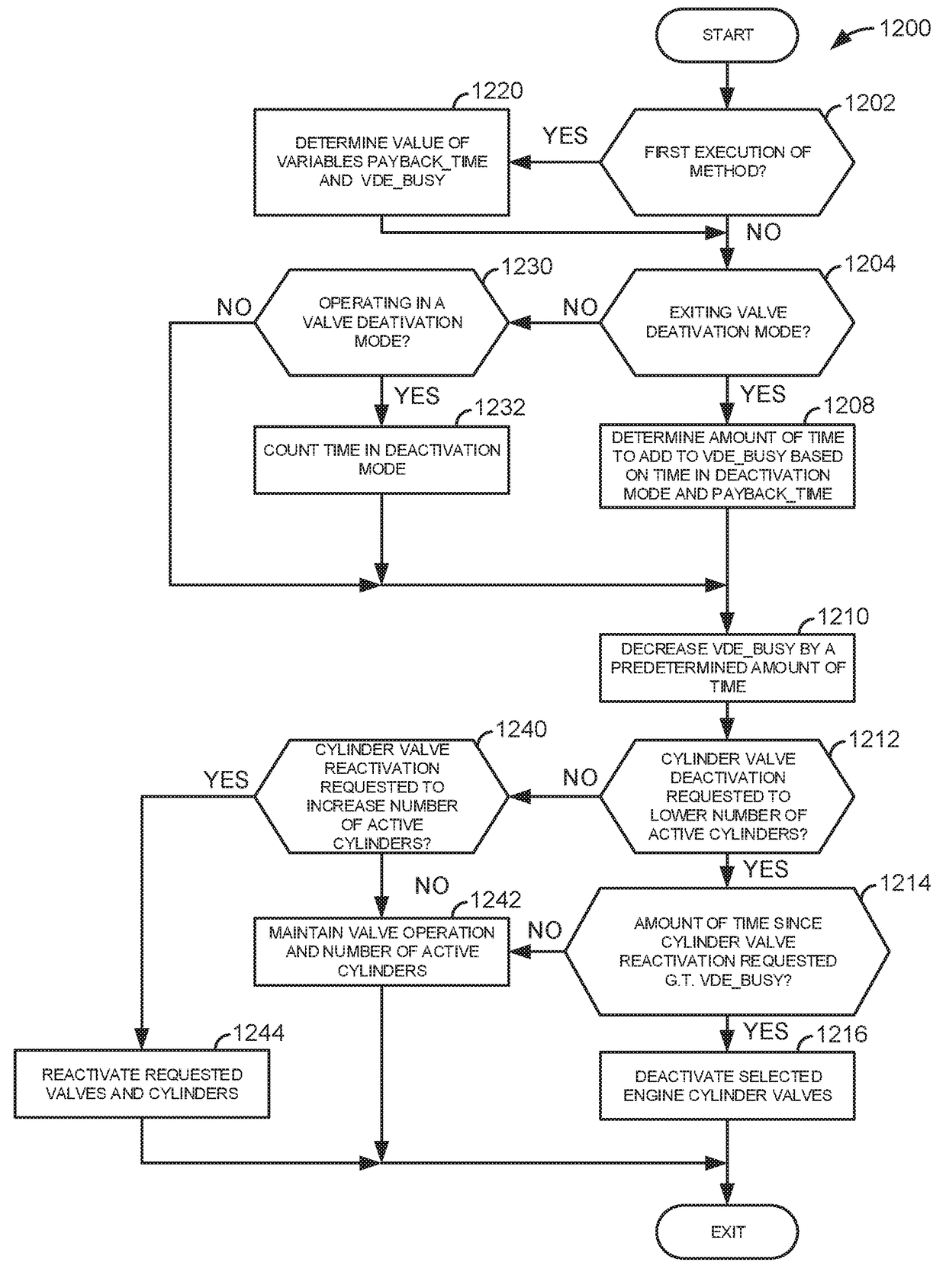
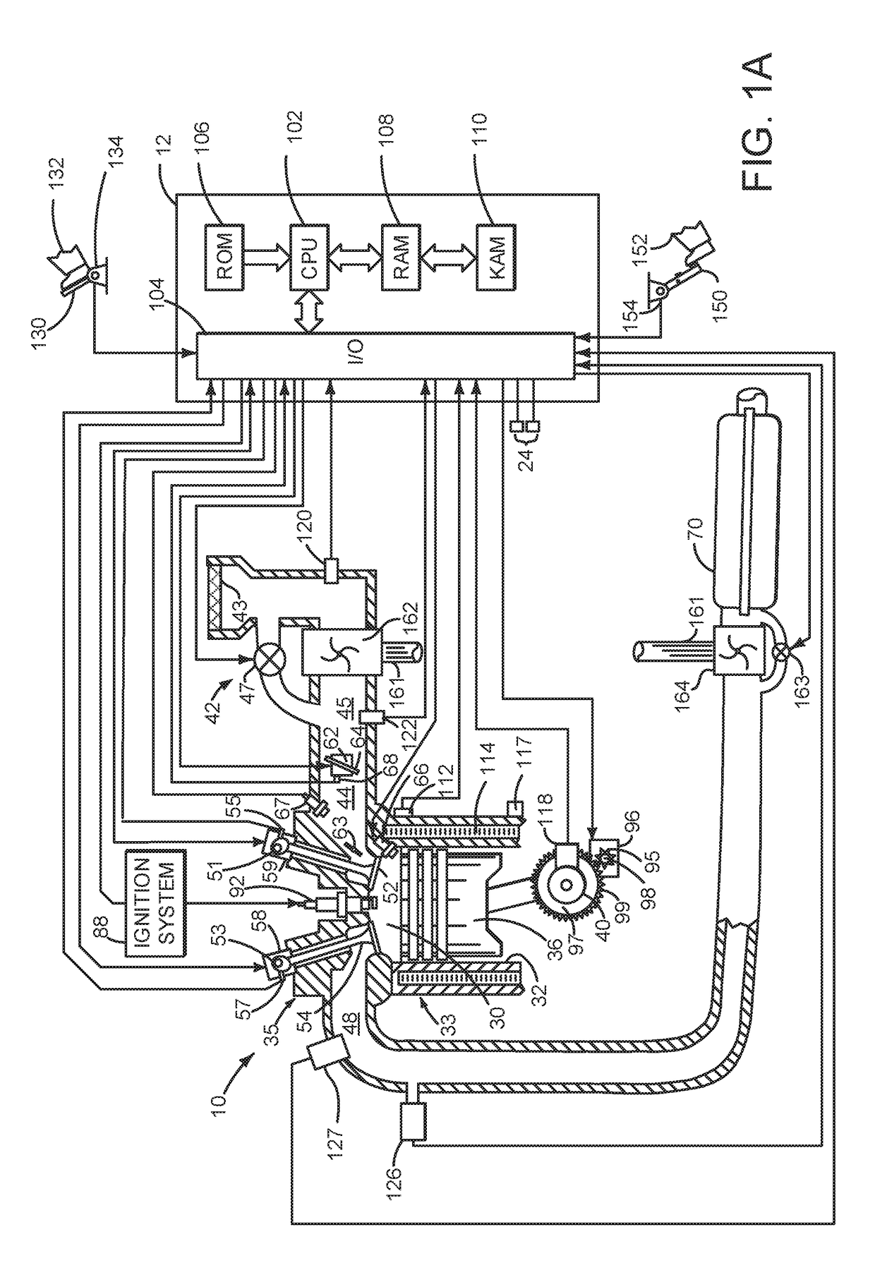
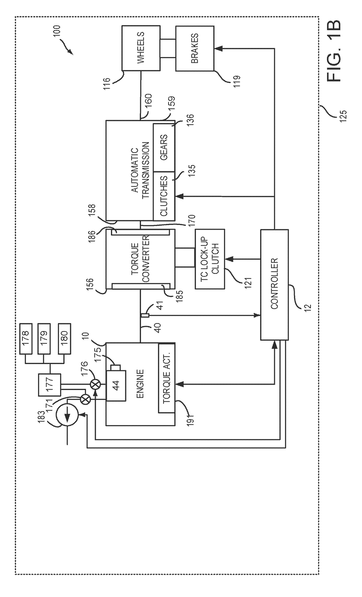
[0059]The present description is related to systems and methods for selectively activating and deactivating cylinders and cylinder valves of an internal combustion engine. The engine may be configured and operate as is shown in FIGS. 1A-6D. Various methods and prophetic operating sequences for an engine that includes deactivating valves are shown in FIGS. 7-42. The different methods may operate cooperatively and with the systems shown in FIGS. 1A-6D.

[0060]Referring to FIG. 1A, internal combustion engine 10, comprising a plurality of cylinders, one cylinder of which is shown in FIG. 1A, is controlled by electronic engine controller 12. Engine 10 is comprised of cylinder head casting 35 and block 33, which include combustion chamber 30 and cylinder walls 32. Piston 36 is positioned therein and reciprocates via a connection to crankshaft 40. Flywheel 97 and ring gear 99 are coupled to crankshaft 40. Starter 96 (e.g., low voltage (operated with less than 30 volts) electric machine) incl...


PUM


Abstract

Systems and methods for operating an engine with deactivating and non-deactivating valves are presented. In one example, engine volumetric efficiency actuators are adjusted in response to a request to activate engine cylinders so that engine intake manifold pressure is drawn down quickly toward its normal state at the engine's present speed and torque.

Description

CROSS REFERENCE TO RELATED APPLICATION[0001]The present application claims priority to U.S. Provisional Patent Application Ser. No. 62 / 347,881, filed on Jun. 9, 2016. The entire contents of the above-referenced application are hereby incorporated by reference in its entirety for all purposes.BACKGROUND AND SUMMARY[0002]Cylinders of an engine may be activated and deactivated via activating and deactivating intake and exhaust valves that control flow to the cylinders. One condition where cylinders may be deactivated is during and immediately after a driver releases an accelerator pedal and driver demand torque is low. The cylinder's intake valves may be closed as part of the cylinder deactivation process. Intake manifold pressure may rise after closing the intake valves because of the absence of air flow through cylinders and because air may leak past the throttle and into the intake manifold. If the cylinders are reactivated after intake manifold pressure rises, the cylinders may pro...

Claims


Application Information

Patent Timeline
Patent Type & Authority Applications(United States)
IPC IPC(8): F02D41/00F02D17/02F02B37/12F02D41/26F01L13/00
CPCF02D41/0087F02D17/02F02D41/0007F02D2200/0406F01L13/0005F02B37/12F01L2013/001F02D41/26F02D13/00F02D13/08F02D2200/101F02D2200/60F01L1/181F01L2001/0535F01L2001/0537F01L2001/186F01L2250/02F01L2250/04F01L2250/06F01L2800/00F01L2800/06F01L2800/08F01L2810/02F01L2820/041F01L2820/042F02D13/04F02D13/06F02D41/126F02D2041/0012F02D2041/0015F02D2200/0411F02D2200/703Y02T10/12
Inventor RICHARDS, ADAM J.ROLLINGER, JOHN ERIC
Owner FORD GLOBAL TECH LLC
Learn More