Unmanned aerial vehicle, motor control device and method

a technology of motor control device and unmanned aerial vehicle, which is applied in the direction of vehicle position/course/altitude control, process and machine control, instruments, etc., can solve the problems of low communication efficiency between the main control unit and the execution unit, complex wiring of the printed circuit board, and high probability of system instability, so as to achieve poor system stability and low communication efficiency

Inactive Publication Date: 2017-12-21
ZEROTECH (SHENZHEN) INTELLIGENCE ROBOT CO LTD
View PDF0 Cites 5 Cited by
  • Summary
  • Abstract
  • Description
  • Claims
  • Application Information

AI Technical Summary

Benefits of technology

[0005]In view of this, one object of the present disclosure is to provide a UAV, a motor control device and method, so as to solve technical problems of a large space occupied by the control circuit for the motors, complicated PCB wiring, poor stability of system, and low efficiency of communication between the main control unit and the execution unit.

Problems solved by technology

In this case, a large space is occupied by a control circuit for the motors, PCB (Printed Circuit Board) wiring is complicated, and the system is likely to be unstable due to cables between the processors.
Furthermore, there may be a low efficiency of communication between the main control unit and the execution unit due to a processing delay of the execution unit.

Method used


Image

  • Unmanned aerial vehicle, motor control device and method
  • Unmanned aerial vehicle, motor control device and method
  • Unmanned aerial vehicle, motor control device and method

Examples


first embodiment

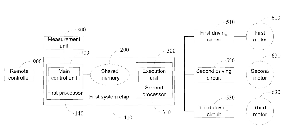
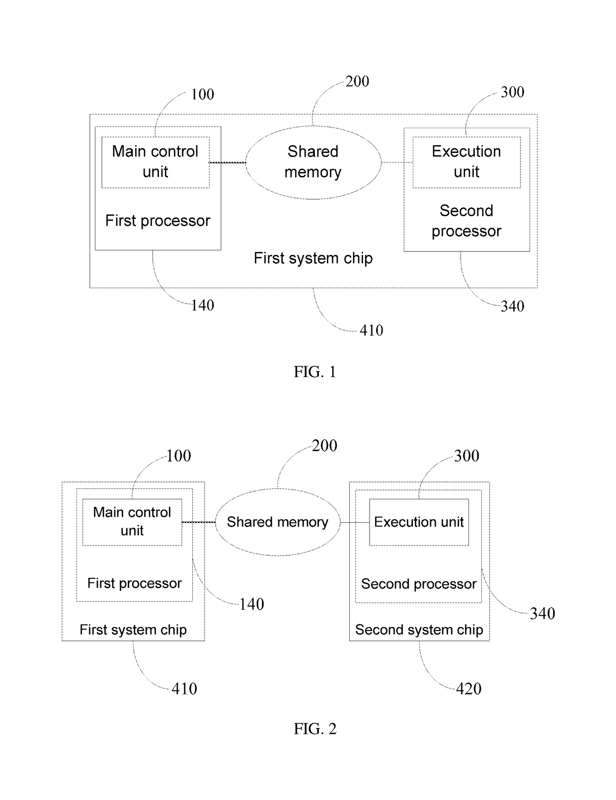
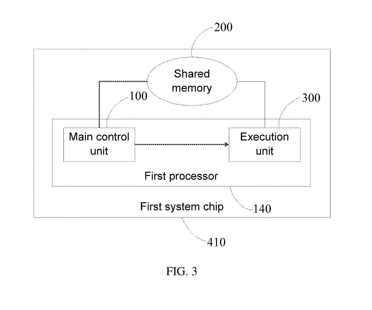
[0023]FIG. 1 shows a structural block diagram of a motor control device provided by an embodiment of the present disclosure. The motor control device provided by the embodiment of the present disclosure is configured to adjust a load into its target attitude by controlling one or more motors on the load. The motor control device provided by the embodiment of the present disclosure includes a main control unit 100, a shared memory 200 and an execution unit 300. The main control unit 100 is provided on a first processor 140, the execution unit 300 is provided on a second processor 340, and the first processor 140, the shared memory 200 and the second processor 340 may be integrated onto a first system chip 410. Data interaction between the main control unit 100 and the execution unit 300 is implemented by means of the shared memory 200.

[0024]As shown in FIG. 2, in another embodiment, the first processor 140 may be provided on the first system chip 410, and the second processor 340 may...

second embodiment

[0046]FIG. 6 shows a flowchart of a motor control method provided by an embodiment of the present disclosure. The motor control method provided by the embodiment of the present disclosure includes the following steps S1 to S3.

[0047]In step S1, current operation parameter information of one or more motors on a load is acquired, and stored in a shared memory.

[0048]In the embodiment of the present disclosure, step S1 may be implemented by an execution unit 300. The current operation parameter information of the motor may include a power of the motor, a frequency of the motor, a voltage and a current of the motor, a current angle data of the motor and the like, where the current angle data of the motor may include an electrical angle of a rotor of the motor. A first motor 610, a second motor 620 and a third motor 630 may be provided with magnetic encoders, where each magnetic encoder may obtain an electrical angle of the rotor of the corresponding motor at any time. The execution unit 3...


PUM


Abstract

The disclosure relates to an unmanned aerial vehicle, a motor control device and method for controlling the same. The motor control method includes: acquiring current attitude information of a load, target attitude information of the load and current operation parameter information of one or more motors on the load, and obtaining control information for controlling the one or more motors in accordance with the acquired information above; transmitting the control information to a shared memory for storage; reading the control information from the shared memory, and controlling operation of the one or more motors in accordance with the control information. In one embodiment, the motor control device does not require cable or PCB wiring to connect a main control unit and an execution unit, reducing the size of hardware. Moreover, with the shared memory, the speed and stability of data interaction between the main control unit and the execution unit may be improved.

Description

CROSS-REFERENCE TO RELATED APPLICATION[0001]The present application claims the priority to a Chinese patent application No. CN201610424304.X, filed with the State Intellectual Property Office on Jun. 15, 2016 and entitled “Unmanned Aerial vehicle, Motor Control Device and Method”, the content of which is hereby incorporated by reference in its entirety.TECHNICAL FIELD[0002]The present disclosure relates to the field of flight control techniques for an unmanned aerial vehicle (UAV), and particularly to a UAV, a motor control device and method.BACKGROUND[0003]A gimbal may be coupled to a UAV, so as to carry a camera, a lighting lamp and the like. The gimbal is generally provided with three motors on a pitching axis, a rolling axis and a yaw axis, respectively. A high speed attitude of the gimbal is achieved by the three motors in such a manner that the three motors perform a locating operation precisely in accordance with a signal received from a controller. The controller generally i...

Claims


Application Information

Patent Timeline
Patent Type & Authority Applications(United States)
IPC IPC(8): G05D1/00B64C39/02H02P5/56
CPCG05D1/0094H02P5/56B64C39/024G05D1/0808H02P5/00H02P29/00B64D47/08B64U2101/30
Inventor SUN, YUZHAN, XIANLONGZHU, XIAO
Owner ZEROTECH (SHENZHEN) INTELLIGENCE ROBOT CO LTD
Why Eureka
Try Eureka