
Interpositional Joint Implant

a technology of interpositional joints and implants, which is applied in the field of orthopaedic methods, systems and devices, can solve the problems of limited implant movement, and achieve the effects of improving the functional result improving the anatomic functionality of the repaired joint, and improving the anatomic results

Inactive Publication Date: 2017-12-28
CONFORMIS
View PDF2 Cites 12 Cited by
  • Summary
  • Abstract
  • Description
  • Claims
  • Application Information

AI Technical Summary

Benefits of technology

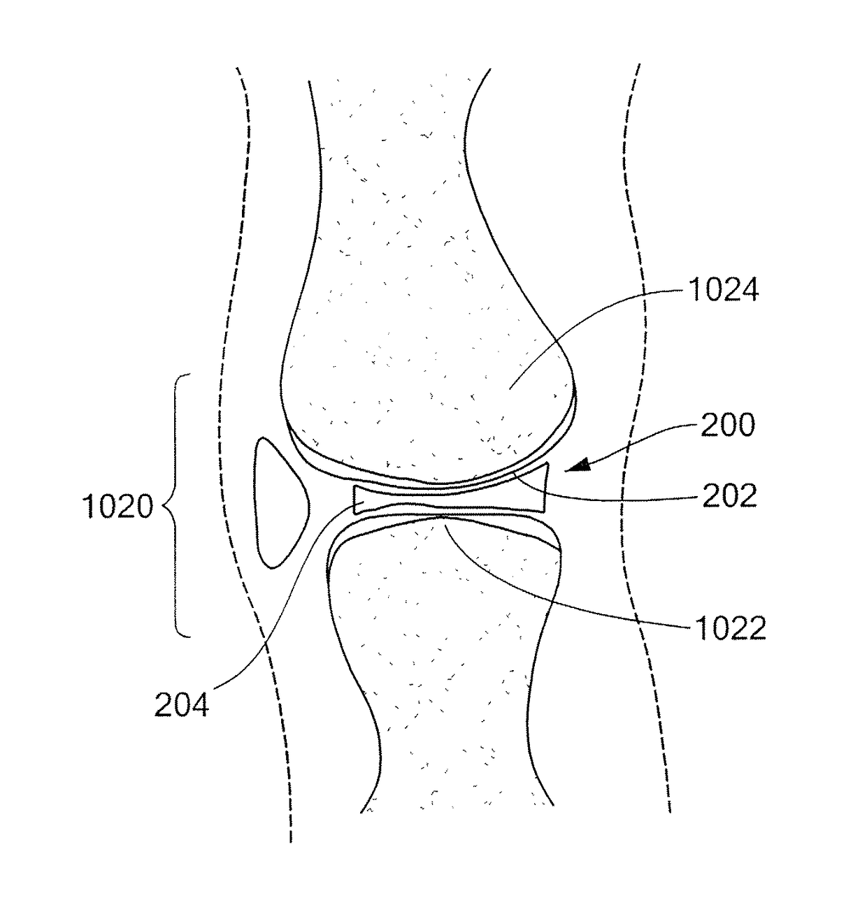
[0020]The present invention provides novel devices and methods for an interpositional implant that replaces a portion of a joint (e.g., such as the meniscus in a knee joint), where the implant(s) achieves an anatomic or near anatomic fit with the surrounding structures and tissues (e.g., subchondral bone and / or cartilage). The to invention also provides for the preparation of an implantation site with a single cut, or a few relatively small cuts. Asymmetrical components can also be provided to improve the anatomic functionality of the repaired joint by providing a solution that closely resembles the natural knee joint anatomy. The improved anatomic results, in turn, leads to an improved functional result for the repaired joint.
[0028]In accordance with related embodiments of the invention, the first articular surface may be a tibial surface, and the second articular surface may be a femoral surface. The first articular surface may include cartilage, or both cartilage and bone. The first implant surface may substantially conform to the first articular surface such that movement of the implant in the joint is limited. The first implant surface may be adapted to substantially remain fixed to the first articular surface upon a load being placed on the second implant surface. Movement of the implant in the joint may be limited without the use of pins, anchors and adhesives. The second surface may be substantially smooth in areas adapted to engage the second articular surface, permitting movement of the second articular surface. The second implant surface may be substantially free of irregularities, roughness, and projections in areas which are adapted to contact the second articular surface. The joint may be a hip joint, ankle joint, toe joint, shoulder joint, elbow joint, wrist joint, or finger joint.
[0033]In accordance with further related embodiments of the invention, the tibial articular surface may include cartilage, or cartilage and bone. The second implant surface may be substantially smooth in areas adapted to engage the femoral articular surface, permitting movement of the femoral articular surface. The second implant surface may be substantially free of irregularities, roughness, and projections in areas which are adapted to contact the femoral articular surface.
[0036]In accordance with further related embodiments of the invention, the second surface may be substantially smooth in areas adapted to engage the second articular surface, permitting movement of the second articular surface. The second implant surface may be substantially free of irregularities, roughness, and projections in areas which are adapted to contact the second articular surface.

Problems solved by technology

The one or more protrusions may be adapted to be inserted into one or more cuts made in the tibial surface, such that motion of the implant is limited.

Method used


Image

  • Interpositional Joint Implant
  • Interpositional Joint Implant
  • Interpositional Joint Implant

Examples


Embodiment Construction

[0057]The following description is presented to enable any person skilled in the art to make and use the invention. Various modifications to the embodiments described will be readily apparent to those skilled in the art, and the generic principles defined herein can be applied to other embodiments and applications without departing from the spirit and scope of the present invention as defined by the appended claims. Thus, the present invention is not intended to be limited to the embodiments shown, but is to be accorded the widest scope consistent with the principles and features disclosed herein. To the extent necessary to achieve a complete understanding of the invention disclosed, the specification and drawings of all issued patents, patent publications, and patent applications cited in this application are incorporated herein by reference.

[0058]As will be appreciated by those of skill in the art, methods recited herein may be carried out in any order of the recited events which ...


PUM

PropertyMeasurementUnit
thicknessaaaaaaaaaa
timeaaaaaaaaaa
thicknessaaaaaaaaaa

Abstract

A method of preparing an interpositional implant suitable for a knee. The method includes determining a three-dimensional shape of a tibial surface of the knee. An implant is produced having a superior surface and an inferior surface, with the superior surface adapted to be positioned against a femoral condyle of the knee, and the inferior surface adapted to be positioned upon the tibial surface of the knee. The inferior surface conforms to the three-dimensional shape of the tibial surface. The implant may be inserted into the knee without making surgical cuts on the tibial surface. The tibial surface may include cartilage, or cartilage and bone.

Description

CROSS-REFERENCE TO RELATED APPLICATIONS[0001]This application is a continuation of U.S. patent application Ser. No. 11 / 688,340, entitled “Interpositional Joint Implant,” filed Mar. 20, 2007, which in turn claims the benefit of U.S. provisional application 60 / 784,255, entitled “Interpositional Joint Implant,” filed Mar. 21, 2006.[0002]U.S. patent application Ser. No. 11 / 688,340 is also a continuation-in-part of U.S. patent application Ser. No. 10 / 997,407, entitled “Patient Selectable Knee Joint Arthroplasty Devices,” filed Nov. 24, 2004, which in turn is a continuation-in-part of U.S. patent application Ser. No. 10 / 752,438, entitled “Patient Selectable Knee Arthroplasty Devices,” filed Jan. 5, 2004, which in turn is a continuation-in-part of U.S. patent application Ser. No. 10 / 724,010, entitled “Patient Selectable Joint Arthroplasty Devices and Surgical Tools Facilitating Increased Accuracy, Speed and Simplicity in Performing Total and Partial Joint Arthroplasty,” filed Nov. 25, 2003...

Claims


Application Information

Patent Timeline
Patent Type & Authority Applications(United States)
IPC IPC(8): A61F2/30A61B5/107A61F2/38A61B5/00A61B5/103A61F2/46
CPCA61F2310/00293A61F2310/00395A61F2310/00011A61F2250/0036A61F2230/0028A61F2230/0015A61F2230/0008A61F2210/0014A61F2210/0004A61F2002/4635A61F2002/30962A61F2002/30957A61F2002/30952A61F2002/30948A61F2002/30884A61F2002/30878A61F2002/30324A61F2002/30163A61F2002/30133A61F2002/30125A61F2002/30092A61F2002/3007A61F2310/00592A61B5/103A61F2310/00383A61F2310/00365A61F2002/30062A61F2/3872A61F2/30942A61F2/30767A61F2/30756A61B5/4528A61B5/4514A61B5/1077A61B5/107A61F2310/00179A61F2002/30179
Inventor STEINES, DANIELLANG, PHILIPPFITZ, WOLFGANG
Owner CONFORMIS
Learn More