Turbine

Active Publication Date: 2017-12-28
HONDA MOTOR CO LTD
View PDF4 Cites 5 Cited by
  • Summary
  • Abstract
  • Description
  • Claims
  • Application Information

AI Technical Summary

Benefits of technology

[0013](1) In the disclosure, the outer duct and the inner duct are disposed in the outflow portion, through which the fluid flows out from the impeller chamber in the outflow direction. The outer duct has the substantially conical inner peripheral surface, which expands in diameter in the outflow direction from the outflow portion. The tubular inner duct extends in the outflow direction from the outflow portion. A space is formed between the outer duct and the inner duct by forming the inner peripheral surface of the outer duct into the substantially conical shape, and the outlet of the bypass flow passage and the waste gate valve which opens and closes the outlet are disposed on the inner peripheral surface of the outer duct. Thus, the fluid that flows out from the outlet of the bypass flow passage flows between the outer duct and the inner duct, and the fluid that flows out from the outflow portion of the impeller chamber flows through the inside of the inner duct. As a result, the flow passage cross-sectional area of the fluid flowing out from the outflow portion of the impeller chamber does not increase abruptly, so that an increase in the pressure loss in the outflow portion can be suppressed. In addition, by disposing the inner duct on the inner side of the outer duct, the inner duct is not directly exposed to the outside air. Thus, the heat in the impeller chamber can be prevented from releasing, and drop of the turbine efficiency can be suppressed. Moreover, by disposing the diffuser flow passage which expands in diameter in the outflow direction in the inner duct at least in a portion between the outflow portion and the distal end portion, the fluid that flows out from the outflow portion can be decelerated in the process of flowing through the diffuser flow passage to increase the static pressure. Therefore, collision loss or friction loss can be reduced.
[0014](2) In the disclosure, the outer flange is disposed on the distal end portion of the outer duct on the side opposite to the outflow portion and the inner flange having one or more through holes are disposed on the distal end portion of the inner duct on the side opposite to the outflow portion, and the inner duct is attached to the outer duct by fixing the inner flange and the outer flange. That is, the fluid that flows out from the bypass flow passage flows between the outer duct and the inner duct and merges with the fluid that flows inside the inner duct through the through holes formed on the inner flange. Therefore, according to the disclosure, the inner duct can be fixed to the outer duct without hindering flow of the fluid that flows out from the bypass flow passage. In addition, because the flange is in contact with the outside by a large area, the temperature drop is large. Thus, in the disclosure, the flanges are disposed on the distal end portions away from the outflow portion as described above to make it more difficult for the heat inside the turbine impeller chamber to be released and reduce the temperature difference between the outer duct and the inner duct, so that reduction of the turbine efficiency can be further suppressed.
[0015](3) According to the disclosure, in the state

Problems solved by technology

Therefore, such a decelerati

Method used


Image

  • Turbine
  • Turbine
  • Turbine

Examples


Embodiment Construction

[0027]Hereinafter, an embodiment of the disclosure is described with reference to the figures.

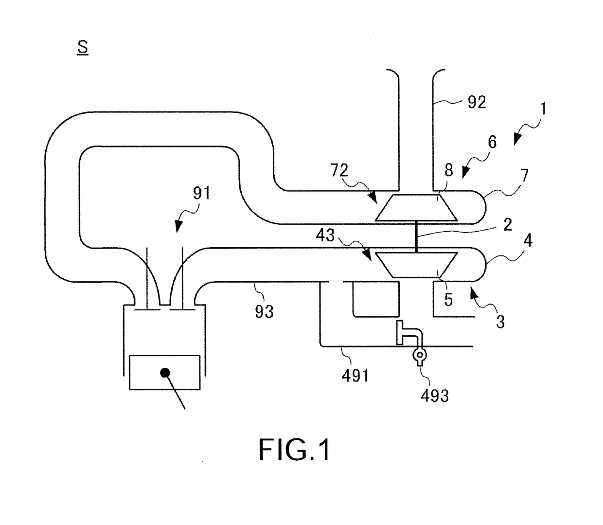
FIG. 1 is a diagram showing the configuration of a supercharging system S of an internal combustion engine 91 to which a turbine 3 is applied according to the present embodiment.

[0028]The supercharging system S includes an intake flow passage 92 that introduces intake air to a combustion chamber of the internal combustion engine 91, an exhaust flow passage 93 that guides an exhaust gas discharged from the combustion chamber of the internal combustion engine 91, and a supercharger 1 that is configured by connecting a compressor 6 disposed in the intake flow passage 92 and the turbine 3 disposed in the exhaust flow passage 93 with a rotating shaft 2 and compresses the intake air by using energy of the exhaust gas.

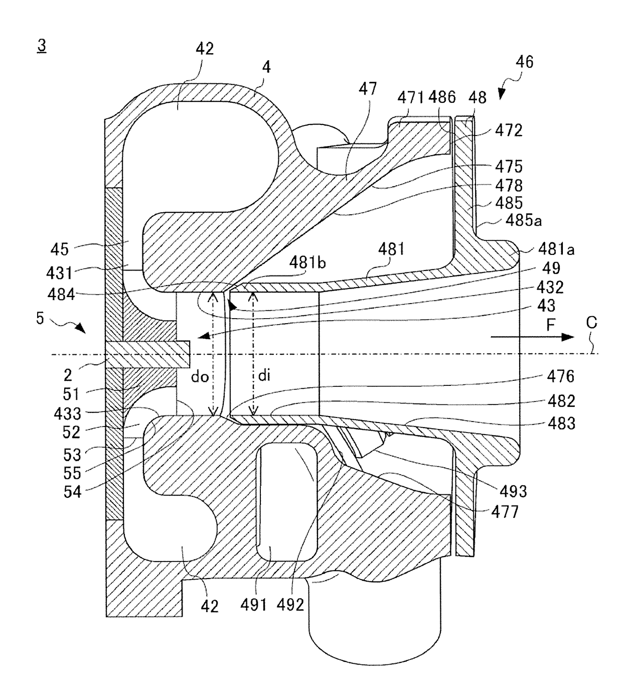
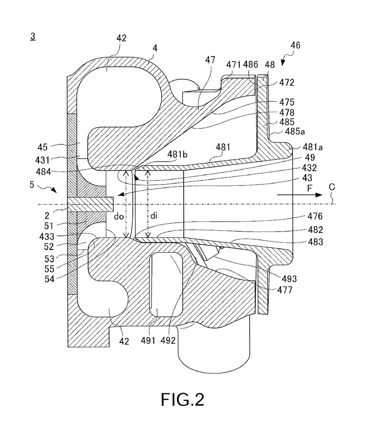
[0029]The turbine 3 includes a turbine housing 4, a turbine impeller 5, a bypass flow passage 491, and a waste gate valve 493. The turbine housing 4 is formed with a turbine impeller...


PUM


Abstract

A turbine (3) includes: a turbine impeller chamber (43) having a tubular outflow portion (432), from which an exhaust gas flows out in an outflow direction (F) substantially parallel to an axis (C) of a turbine impeller (5); a bypass flow passage (491) bypassing the inside of the turbine impeller chamber; an outer duct (47) having an inner peripheral surface (475) that expands in diameter in the outflow direction from the outflow portion; and an inner duct (48) that extends in the outflow direction from the outflow portion. A diffuser flow passage (483) that expands in diameter in the outflow direction is disposed in the inner duct at least in a portion between the outflow portion and a distal end portion (481a). An outlet (492) of the bypass flow passage and a waste gate valve (493) that opens and closes the outlet are disposed on the inner peripheral surface.

Description

CROSS-REFERENCE TO RELATED APPLICATION[0001]This application claims the priority benefit of Japan application serial no. 2016-127493, filed on Jun. 28, 2016. The entirety of the above-mentioned patent application is hereby incorporated by reference herein and made a part of this specification.BACKGROUND OF THE DISCLOSUREField of the Disclosure[0002]The disclosure relates to a turbine and more particularly relates to a turbine including a bypass flow passage that bypasses the inside of an impeller chamber, which houses an impeller, and a waste gate valve that opens and closes the bypass flow passage.Description of Related Art[0003]A supercharging system of an internal combustion engine is provided with a supercharger, in which a compressor impeller disposed in an intake flow passage of the internal combustion engine and a turbine impeller disposed in an exhaust flow passage are connected by a rotating shaft. In the supercharging system, an exhaust gas of the internal combustion engin...

Claims


Application Information

Patent Timeline
IPC IPC(8): F01D25/30F01D17/10F01D5/04F01D15/08F02B37/18F02B33/40
CPCF01D25/30F02B33/40F01D5/043F01D17/105F01D15/08F02B37/183F05D2220/40Y02T10/12
Inventor ITOH, NAOKIKUNO, NAOKISAKAKIBARA, TAKASHI
Owner HONDA MOTOR CO LTD
Why Eureka
Try Eureka