Two-stage heating geothermal system using geothermal energy

a geothermal system and two-stage technology, applied in the field of two-stage heating geothermal system using geothermal energy, can solve the problems of large amount of energy spent heating, increase in the condensation temperature of freon, insignificant increase in the compression ratio of a compressor, and insignificant decrease in the efficiency (cop) so as to improve the operating efficiency of the two-stage heating geothermal system and improve the efficiency of the geothermal heat pump. ,

Inactive Publication Date: 2017-12-28
J&G CO LTD
View PDF0 Cites 11 Cited by
  • Summary
  • Abstract
  • Description
  • Claims
  • Application Information

AI Technical Summary

Benefits of technology

[0009]Since the two-stage heating geothermal system using geothermal energy according to an aspect of the present disclosure includes the geothermal heat exchanger, the geothermal heat pump, and the booster heat pump, two-stage heating can be performed by the booster heat pump by recycling waste heat from the condenser that would otherwise be discarded to the underground during the cooling operation of the geothermal heat pump. It is thereby possible to significantly improve the operating efficiency of the two-stage heating geothermal system using geothermal energy without an adverse effect on the operating efficiency of the booster heat pump. In addition, refrigerant flowing toward the geothermal heat exchanger can be precooled due to heat absorption by the booster heat pump, thereby further improving the operating efficiency of the geothermal heat pump. Since medium-temperature condensation heat that would otherwise be dissipated to the underground is heated to a higher temperature, a speedier response than heating low-temperature refrigerant can be achieved. In addition, during the heating operation of the geothermal heat pump, the geothermal heat pump and the booster heat pump can share the geothermal heat exchanger via a single line, such that geothermal heat can be efficiently absorbed and hot water supply, auxiliary heating, and the like can be controlled to be completely independent of main heating.

Problems solved by technology

First, the temperature of heat discarded from the geothermal heat pump to the underground is about 25° C. to about 30° C., which has a significant difference from the temperature of hot water necessary for hot water supply or auxiliary heating, which is about 40° C. to about 50° C. Since repetitive heating is necessary to raise the temperature to a desirable temperature, a large amount of energy is spent in heating.
Second, since the temperature of hot water necessary for hot water supply or auxiliary heating is about 40° C. to about 50° C., a condensation temperature necessary for the geothermal heat pump must be significantly raised to a level of about 35° C. to about 50° C., which is the temperature of a typical operation. This causes an increase in the condensation temperature of Freon, thereby leading to an insignificant increase in the compression ratio of a compressor and an insignificant decrease in the efficiency (COP) of the geothermal heat pump. Accordingly, the amount of power consumed for the cooling operation of the geothermal heat pump is significantly increased.
Furthermore, a separate heat pump for hot water supply is not provided.
In a heating mode in the winter, hot water produced for heating by the geothermal heat pump must be divided for heating and hot water supply, thereby reducing the usability of a geothermal heat source.
In addition, when the temperature of water for heating is different from the temperature of water for hot water supply, it may be difficult to perform independent temperature control.

Method used


Image

  • Two-stage heating geothermal system using geothermal energy
  • Two-stage heating geothermal system using geothermal energy
  • Two-stage heating geothermal system using geothermal energy

Examples


first embodiment

[0046]Hereinafter, a two-stage heating geothermal system using geothermal energy according to another embodiment will be described with reference to the accompanying drawings. In the following, descriptions of some features will be omitted when they are identical to those of the above-described first embodiment of the present disclosure.

second embodiment

[0047]FIG. 5 is a schematic view illustrating a two-stage heating geothermal system using geothermal energy according to a

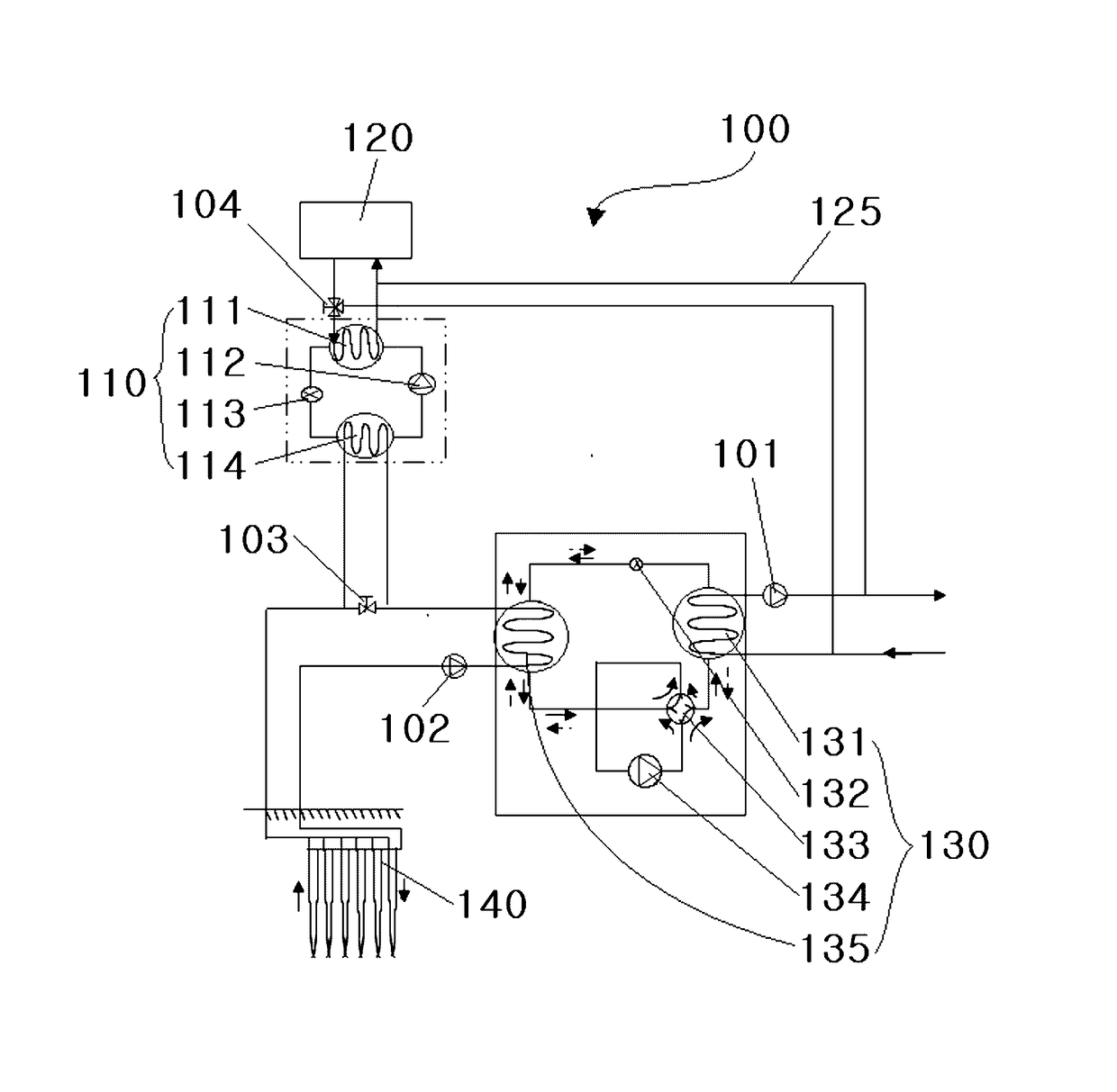
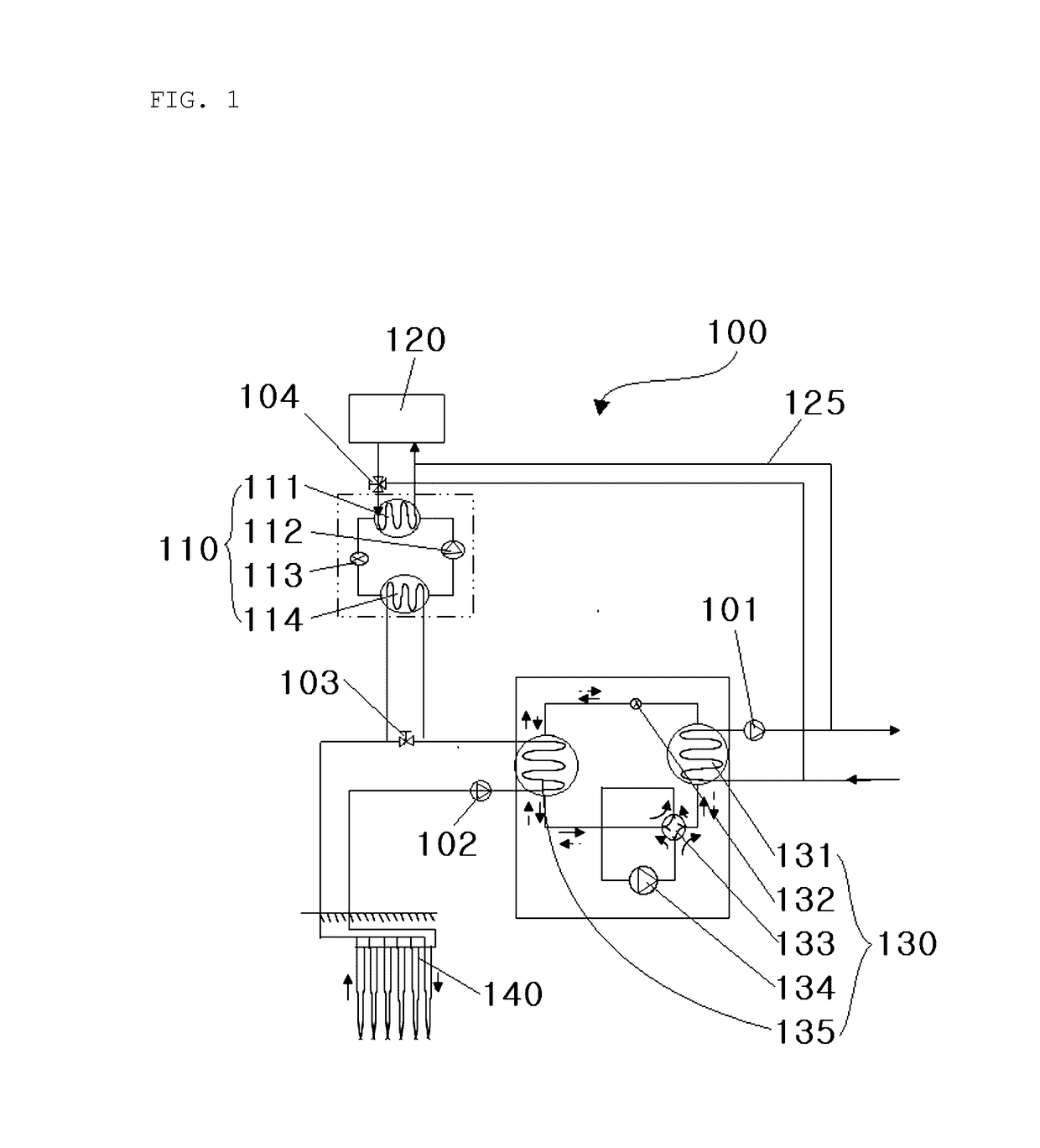
[0048]Referring to FIG. 5, the two-stage heating geothermal system using geothermal energy according to the present embodiment includes a triple heat exchanger 250 disposed on a pipe, by which a geothermal heat pump 230 and a booster heat pump 210 are connected.

[0049]The triple heat exchanger 250 is configured such that heat exchange occurs among three components, i.e. a pipe extending from a geothermal heat exchange-side geothermal heat exchanger 235 of the geothermal heat pump 230 to a geothermal heat exchanger 240, a heat source-side booster heat exchanger 214 of the booster heat pump 210, and a low-temperature hot water tank 260, such that waste heat generated by the geothermal heat exchanger 240 can be provided for hot water supply, auxiliary heating, and the like by the booster heat pump 210 while being used for low-temperature heating and the like in the l...

third embodiment

[0053]FIG. 6 is a schematic view illustrating a two-stage heating geothermal system using geothermal energy according to a

[0054]Referring to FIG. 6, according to the present embodiment, a booster heat pump 310 is connected in parallel to a pipe, by which a geothermal heat pump 330 and a geothermal heat exchanger 340 are connected.

[0055]Reference numeral 370 is an opening and closing valve able to control the flow of refrigerant from the geothermal heat pump 330 to the booster heat pump 310. The opening and closing valve 370 may be implemented as a three-way valve.

[0056]While the present disclosure has been illustrated and described with respect to the specific exemplary embodiments, it will be apparent to a person having ordinary skill in the art that many modifications and variations are possible without departing from spirits and scopes of the present disclosure defined by appended claims. It is definitely noted that such modifications and variations are included within the scope ...


PUM


Abstract

Disclosed is a two-stage heating geothermal system using geothermal energy. The two-stage heating geothermal system includes a geothermal heat exchanger, a geothermal heat pump, a booster heat pump, a bypass line, and a bypass line opening and closing valve. The operating efficiency of the two-stage heating geothermal system using geothermal energy is significantly improved. Hot water supply, auxiliary heating, and the like are controlled to be completely independent of main heating.

Description

TECHNICAL FIELD[0001]The present disclosure relates to a two-stage heating geothermal system using geothermal energy in which a hot water production method having ultrahigh efficiency is realized by recycling waste heat of a geothermal heat pump.BACKGROUND ART[0002]A two-stage heating geothermal energy system using geothermal energy refers to a system able to provide cooling and heating as well as hot water to users using heat obtained by heat exchange conducted underground. Disclosed as examples of the two-stage heating geothermal energy system are Korean Patent No. 10-0998483 (titled: “MULTI-MODULE COOLING AND HEATING SYSTEM USING GEOTHERMAL HEAT EXCHANGE PUMP”), Korean Patent No. 10-1052465 (titled: “DUAL-TYPE HEAT PUMP SYSTEM USING HEAT TRANSFER MEDIUM AND REFRIGERANT”), Korean Patent No. 10-0900441 (titled: “HEAT PUMP COOLING AND HEATING SYSTEM USING GEOTHERM”), and the like.[0003]Condensation heat created while a geothermal heat pump is providing cooling to a user side has bee...

Claims


Application Information

Patent Timeline
Patent Type & Authority Applications(United States)
IPC IPC(8): F24J3/08F25B30/00F25B13/00F25B27/00F25B41/04F25B41/00
CPCF24J3/081F25B30/00F25B41/04F25B13/00F25B41/00F25B27/00F25B30/06F25B2313/002F25B2313/003F25B2313/004F25B2339/047F25B2400/06F24D3/08F24D2200/11F24D2200/123F24D17/02F24D3/18F24T10/00Y02B30/12Y02B10/40Y02E10/10F25B41/20F25B30/02F24D17/00
Inventor SHIN, JEONGSOOPARK, JONG-WOO
Owner J&G CO LTD
Why Eureka
Try Eureka