Separated Parallel Beam Generation for Atom Interferometry

a parallel beam and atom interferometer technology, applied in the field of atomic interferometer, can solve the problems of sensor drift and/or signal loss, limit system sensitivity,

Inactive Publication Date: 2017-12-28
CHARLES STARK DRAPER LABORATORY
View PDF8 Cites 17 Cited by
  • Summary
  • Abstract
  • Description
  • Claims
  • Application Information

AI Technical Summary

Benefits of technology

[0019]In accordance with yet another embodiment of the invention, configuring the at least one alignment-insensitive beam routi

Problems solved by technology

Maintaining parallel alignment of these laser beams is often critical for proper operation of the device, since loss of parallelism can result in sensors drift and/or loss of signal.
Configurations in which external facto

Method used


Image

  • Separated Parallel Beam Generation for Atom Interferometry
  • Separated Parallel Beam Generation for Atom Interferometry
  • Separated Parallel Beam Generation for Atom Interferometry

Examples


Embodiment Construction

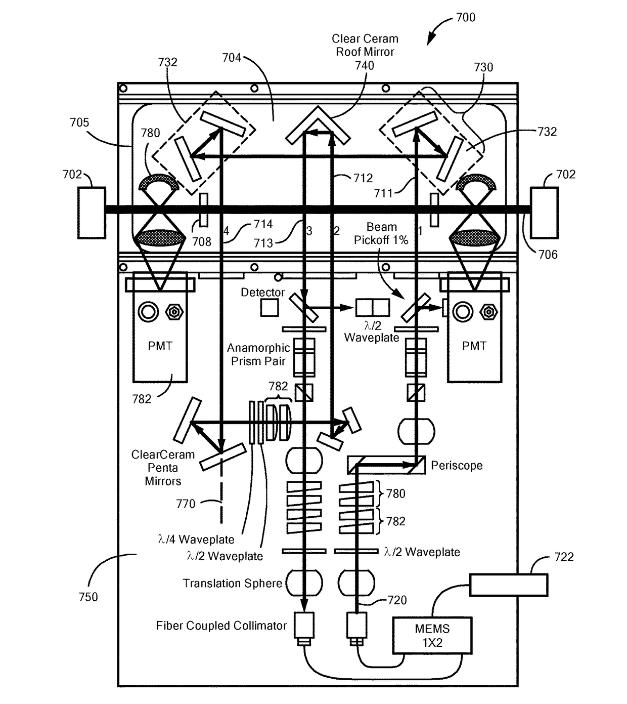
[0008]In accordance with embodiments of the present invention, an atomic interferometer is provided that has an ensemble of atoms and a laser beam traversing the ensemble of atoms in a first laser beam path. An optical components train, comprising at least one alignment-insensitive beam routing element, is configured to reflect the laser beam along a second laser beam path that is anti-parallel with respect to the first laser beam path. The atomic interferometer also has an entirely refractive alignment element for steering the laser beam into the optical components train, and a detector configured to detect spontaneous fluorescence emitted by atoms within the ensemble of atoms after traversal of the first and second laser beam paths.

[0009]In accordance with certain other embodiments of the present invention, the ensemble of atoms may include a beam of atoms traversing a vacuum chamber, and the alignment-insensitive beam routing element may include at least one of a pentaprism pair,...


PUM


Abstract

An atomic interferometer and methods for measuring phase shifts in interference fringes using the same. The atomic interferometer has a laser beam traversing an ensemble of atoms along a first path and an optical components train with at least one alignment-insensitive beam routing element configured to reflect the laser beam along a second path that is anti-parallel with respect to the first laser beam path. Any excursion from parallelism of the second beam path with respect to the first is rigorously independent of variation of the first laser beam path in yaw parallel to an underlying plane.

Description

[0001]The present application claims priority from U.S. Provisional Application Ser. No. 62 / 353,415, filed Jun. 22, 2016, and incorporated herein by reference.TECHNICAL FIELD[0002]The present invention relates to atomic interferometry, and, more particularly, to optical configurations that enable unprecedented precision and stability of atomic interferometric measurements.BACKGROUND ART[0003]Atom interferometers use the wave character of atoms as a technique for precision measurements in geodesy, inertial navigation, time, and fundamental physics. Atom interferometry is typically performed by manipulating quantum objects, such as atoms, by applying one or more sequences of coherent beam splitting sequences. After being split into two parts by a coherent beam-splitting process, the atomic wavepackets move along two different paths for an interrogation time, during which the two atomic wavepackets accumulate different phases.[0004]Some of the most precise measurements of physical quan...

Claims


Application Information

Patent Timeline
IPC IPC(8): G01N21/64G01B9/02G21K1/00
CPCG01N21/6404G01B9/02015G01N21/645G01N2201/06113G01B2290/55G01N2021/6463G21K1/006G01B9/02061G01V7/00G01C19/58
Inventor SINCLAIR, MATTHEW A.KELSEY, ADAMSTONER, RICHARD E.
Owner CHARLES STARK DRAPER LABORATORY
Why Eureka
Try Eureka